

Engineering drawing basics explained for reading technical drawings views lines and standards in CAD and drafting
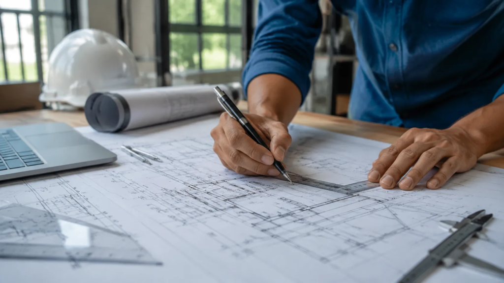
Production Capabilities & Technical Specifications
When you submit a drawing in engineering to us, your technical specifications dictate our manufacturing route. We turn your 2D CAD drawing concepts into physical components using advanced investment casting and precision CNC machining.
Material Matrix & Metal Specifications
Our foundry processes a wide range of compliant metals frequently specified on an orthographic projection sheet or mechanical design draft.
| Metal Group | Common Alloy Grades | Core Manufacturing Benefits |
|---|---|---|
| Stainless Steel | 304, 316, 17-4 PH | Superior corrosion resistance and high tensile strength. |
| Carbon Steel | WCB, 1020, 1045 | Excellent machinability and structural cost-efficiency. |
| Alloy Steel | 4140, 8620 | Enhanced wear resistance and deep hardenability. |
| Aluminum Alloys | A356, 6061-T6 | Lightweight with excellent thermal conductivity. |
Precision Tolerance Capabilities
We hold tight tolerances directly from your technical specification drawing, minimizing the need for extensive post-processing.
- Investment Casting Tolerance: Maintained to ISO 8062-3 DCTG 4 to DCTG 6 standards, ensuring exceptional net-shape accuracy straight from the mold.
- Precision CNC Machining: Delivers final component tolerances down to ±0.005 mm (±0.0002 inches) for critical bores, faces, and alignment features.
- Geometric Control: Full compliance with your specified GD&T (Geometric Dimensioning and Tolerancing) callouts, including strict flatness, parallelism, and true position requirements.
Scalable Production Volume
Our production line adapts to your product lifecycle stage, matching the exact delivery requirements on your production drawing.
- Rapid Prototyping: Fast-turnaround validation units using 3D-printed patterns to test your mechanical manufacturing drawing before hard tooling.
- Low-Volume Runs: Flexible setup options for bridge production and specialized, low-quantity industrial builds.
- High-Volume Series Production: Automated investment casting lines and multi-axis CNC cells optimized for continuous, large-scale manufacturing runs.
How We Interpret and Process Your Engineering Drawings

Turning a complex drawing in engineering into a flawless metal component requires absolute precision from day one. We take your 2D CAD drawing or technical drawing and push it through a strict, four-step manufacturing pipeline to ensure the final part matches your exact design intent.
Step-by-Step Blueprint Execution
- Step 1: Technical Review & GD&T Analysis
Our engineering team digs deep into your mechanical manufacturing drawing to analyze Geometric Dimensioning and Tolerancing (GD&T) notes. We catch potential interference or machining issues before metal is poured. - Step 2: CAE Simulation & Mold Design
We transform your blueprint specifications into digital tooling layouts. Computer-Aided Engineering (CAE) software simulates the metal flow, eliminating defects like porosity before cutting the physical mold. - Step 3: Precision Execution (14-Step Investment Casting)
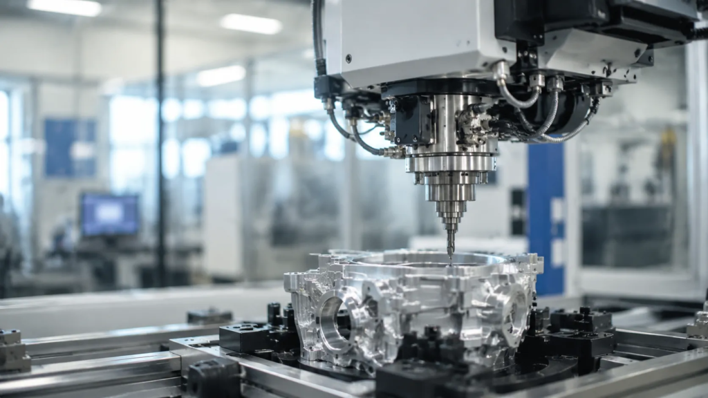
Using the approved investment casting drawing, we build high-precision wax patterns and ceramic shells. This classic, 14-step process delivers near-net-shape components with excellent surface finishes. - Step 4: Sub-MM CNC Post-Machining
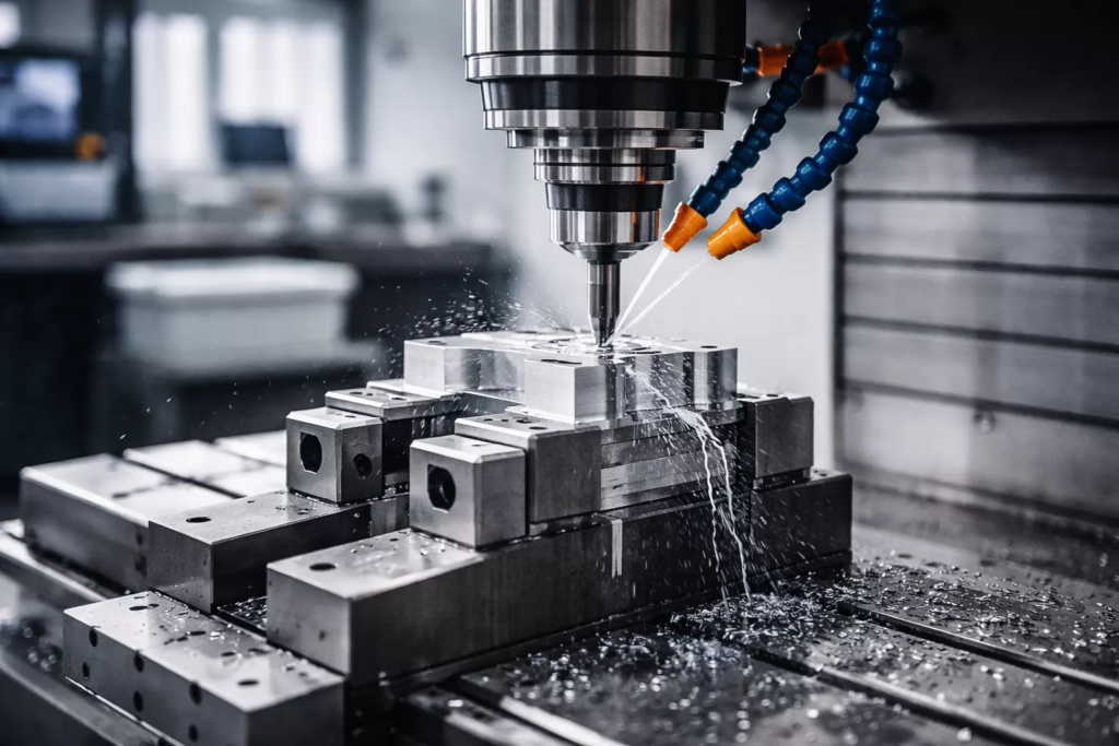
For ultra-tight tolerances, we follow the CNC machining blueprint instructions on our high-speed milling and turning centers, achieving tight, sub-millimeter accuracy where your design demands it.
Workflow & Capability Overview
| Processing Stage | Key Focus Area | Target Output |
|---|---|---|
| Blueprint Intake | Initial review of the component blueprint | Verification of tolerances and GD&T feasibility |
| Tooling & Mold Setup | Converting 3D data and orthographic projection sheets | High-durability tooling designed for zero-defect casting |
| Foundry Production | Advanced investment casting at Precision Vast | Near-net-shape metal parts built to your exact alloy spec |
| CNC Machining | Meeting critical dimensions on the mechanical design draft | Sub-mm precision for threads, bores, and mating surfaces |
Quality Inspection of Your Technical Drawing Specifications
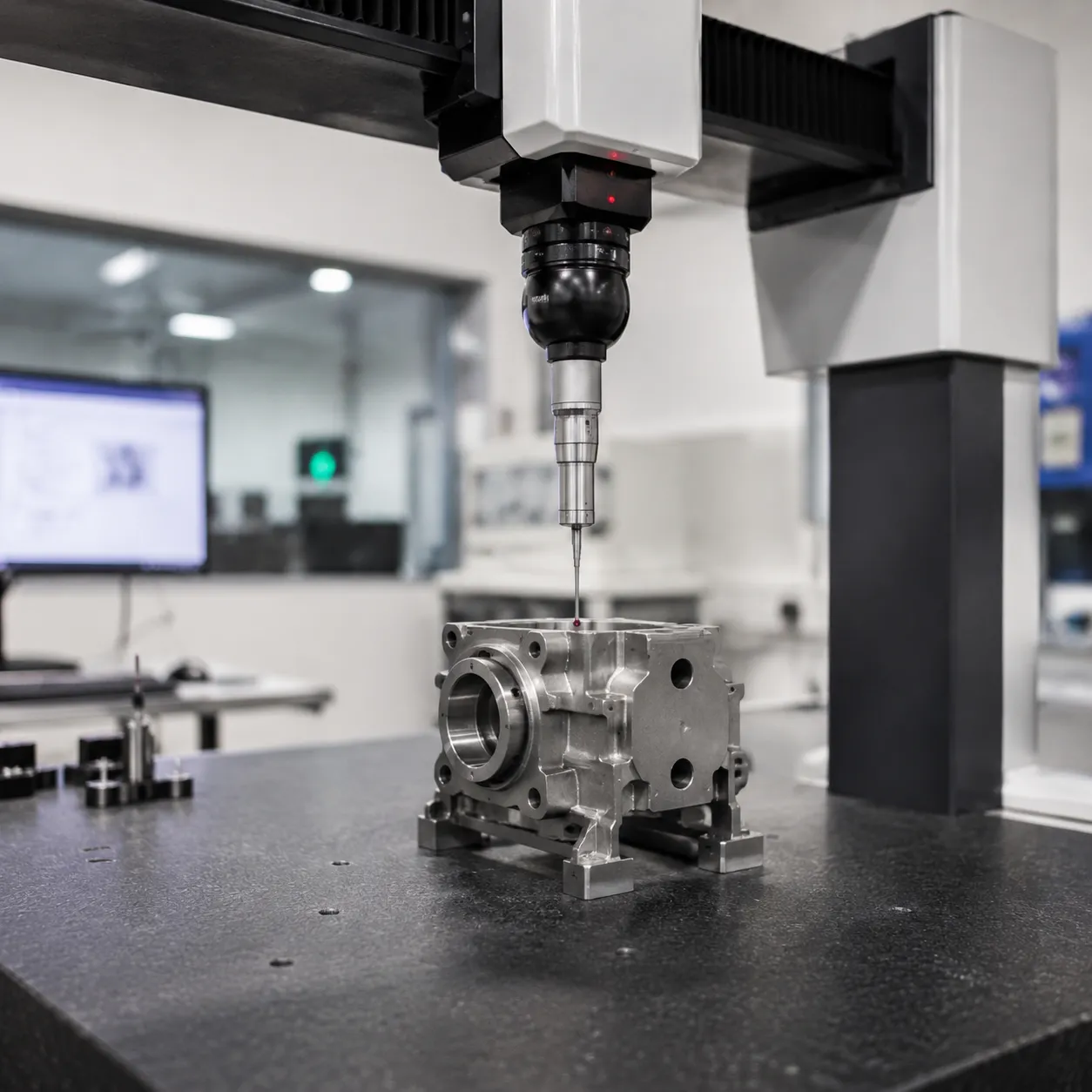
We don’t just read your drawing in engineering—we verify every single line of it. Our quality control team matches your exact engineering blueprint requirements against the final physical part using advanced metrology and testing.
Here is how we validate your precision manufacturing blueprint specs:
Dimensional Verification with CMM
We use automated Coordinate Measuring Machines (CMM) to check complex geometries against your 2D CAD drawing. This ensures that tight tolerances and strict GD&T (Geometric Dimensioning and Tolerancing) callouts are perfectly met.
Structural Integrity & Certified Compliance
Every component blueprint undergoes rigorous testing to guarantee internal soundness and full industry alignment.
- Non-Destructive Testing (NDT): X-ray and liquid penetrant inspections find hidden internal defects without damaging the part.
- ISO 9001:2015 Certified: Our entire inspection workflow follows strict quality management systems for full traceability.
| Inspection Type | Equipment / Method | Target Specification |
|---|---|---|
| Dimensional Audit | CMM & Optical Scanners | GD&T Profiles, Linear Tolerances |
| Surface Integrity | Liquid Penetrant Testing | Surface Cracks, Porosity |
| Internal Soundness | X-Ray / Radiography | Internal Voids, Inclusion Defects |
| Material Validation | Spectrometry Testing | Chemical Composition Compliance |
Target Industries for Your Technical Drawing Specifications
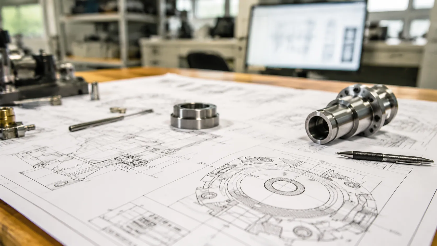
We turn your complex drawing in engineering documents into high-performance physical parts. Different industries demand different standards, and our facility is equipped to hit every exact detail on your engineering blueprint.
Aerospace & Defense
High-stress environments leave zero room for error. We use your mechanical manufacturing drawing packages to produce flight-ready components that withstand extreme force and temperature cycles. Common parts: Turbine blades, structural brackets, fuel system components. Key focus: Absolute structural integrity and strict adherence to GD&T callouts.
Medical Equipment
Surgical tools and implantable devices require both geometric perfection and bio-safety. We translate your 2D CAD drawing specifications into smooth, intricate hardware. Common parts: Surgical implants, orthopedics, diagnostic equipment housings. Key focus: Biocompatible metals and flawless surface finishes right out of the mold.
Pumps, Valves, & Fittings
Heavy-industrial applications need rugged reliability. We cast and machine heavy-duty hardware based on your production drawing requirements to handle high pressure and constant fluid flow. Common parts: Impellers, valve bodies, pressure flanges. Key focus: Internal integrity, pressure-tight sealing, and wall thickness consistency.
Automotive & Marine Hardware
Exposure to salt, moisture, and road grit requires smart material choices and tight tolerances. Your component blueprint guides our manufacturing to ensure parts survive harsh outdoor environments. Common parts: Steering knuckles, marine propellers, custom brackets. Key focus: Corrosion-resistant alloys and high-yield strength.
Frequently Asked Questions (FAQs)
What file formats do you accept for engineering drawings?
We accept both 3D models and 2D CAD drawing formats to kickstart our manufacturing review. For the fastest turnaround on your drawing in engineering packages, we prefer native digital files.
| File Type | Preferred Formats | Alternate Formats |
|---|---|---|
| 3D CAD Model | .STEP, .IGES, .X_T (Parasolid) | .PRT, .SLDPRT, .IPT |
| 2D Technical Drawing | .PDF, .DWG, .DXF | .TIFF |
How do you handle strict GD&T requirements?
Our engineering team reviews every engineering blueprint for Geometric Dimensioning and Tolerancing (GD&T) compliance during print intake. We translate your specified datums, flatness, and runout tolerances directly into our tooling design and CNC fixture setups. Critical dimensions highlighted on your technical drawing are mapped straight to our Coordinate Measuring Machine (CMM) for automated inspection, ensuring the final part matches your exact mechanical manufacturing drawing specs.
What is your typical turnaround time for a blueprint quote?
- Standard Request: 24 to 48 hours for most production drawing packages.
- Complex Assemblies: 3 to 5 business days for intricate multi-part configurations or highly detailed investment casting drawing specifications.
 German
  English