Introduction
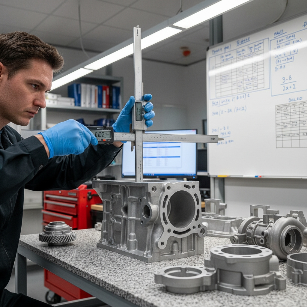
Precision is the enemy of the foundry floor when you don’t have the right data. Imagine you are a foundry engineer staring at a fresh batch of complex housings, only to find that a critical mounting boss has pulled away from tolerance by a mere millimeter, rendering the entire part scrap. This isn’t just a dimensional error; it is a direct hit to your profit margin, wasting expensive alloy, delaying production schedules, and damaging your reputation with clients who demand exact specifications.
The good news is that you can eliminate this guesswork. By understanding the physics of phase change and applying precise calculation formulas, you can predict and compensate for aluminum casting shrinkage with near-perfect accuracy. Drawing on decades of sand casting metallurgy, this guide breaks down the exact math and methods professional foundries use to ensure every pour results in a perfect fit.
What is aluminum casting shrinkage in sand casting?
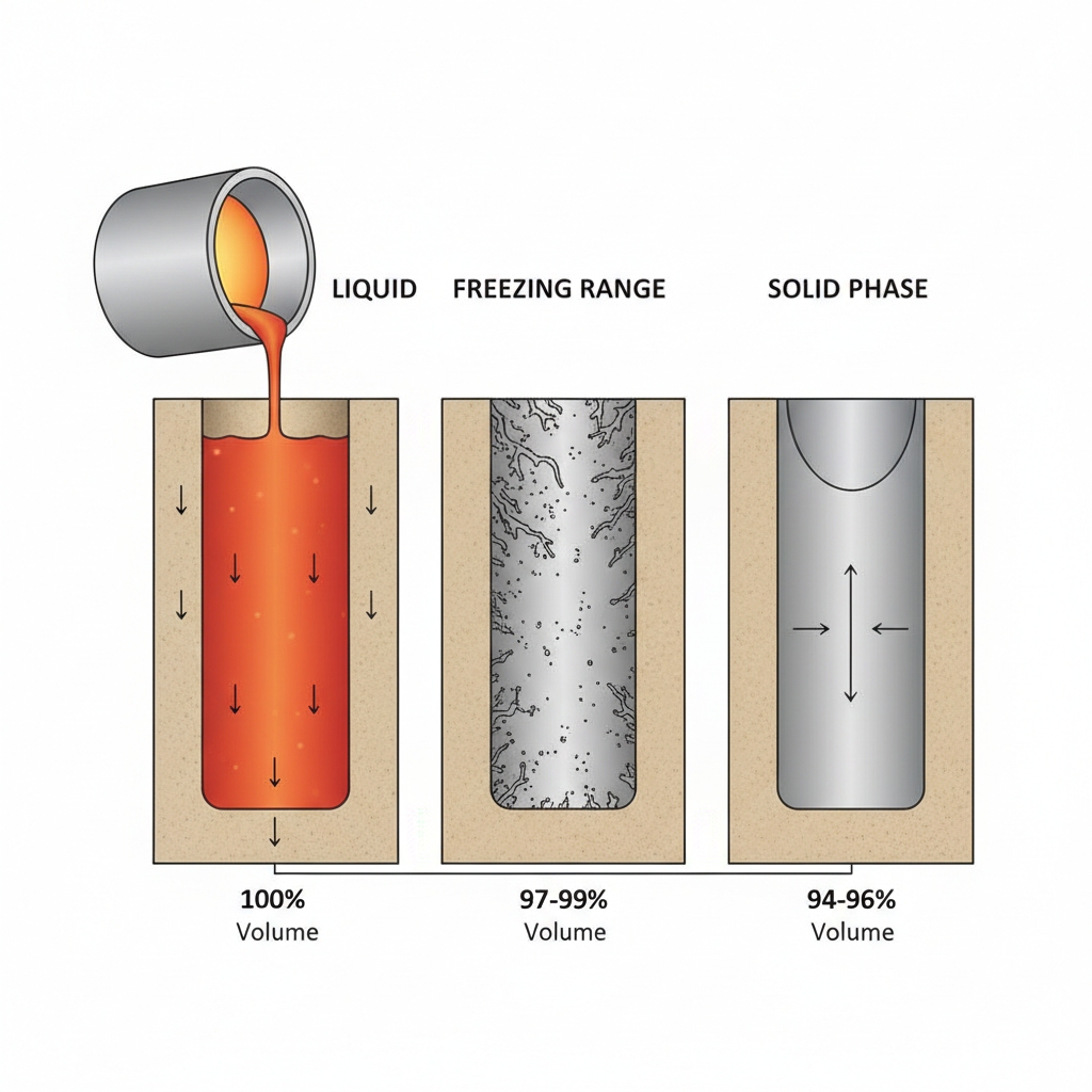
Aluminum casting shrinkage is the predictable reduction in the volume of metal as it transitions from a superheated liquid state to a solid at room temperature. In the aluminum casting process , this phenomenon occurs because the atomic structure of the metal becomes denser as it cools, pulling mass inward and potentially altering the final dimensions of your part if not accounted for.
But here’s the thing: Shrinkage is not a defect in itself; it is a physical certainty that you must manage. If you fail to calculate the volume loss correctly, your sand mold will produce parts that are undersized or riddled with internal voids.
Understanding volume reduction
The physics behind this are straightforward but unforgiving. As molten aluminum cools, its atoms vibrate less and pack tighter together.
- Liquid state: Atoms are energetic and spread out.
- Solid state: Atoms lock into a crystalline lattice structure.
This packing efficiency results in a specific volume decrease. You need to treat this as a design parameter, not an afterthought.
Why does specific volume decrease?
Specific volume decreases because the density of the solid alloy is significantly higher than that of the liquid.
- Aluminum density (Liquid): ~2.3 g/cm³
- Aluminum density (Solid): ~2.7 g/cm³
Imagine this: You fill a water balloon and freeze it; the ice expands. Metal does the opposite; it contracts, meaning your mold cavity must always be larger than the final desired part.
Key Takeaway:Understanding that shrinkage is a density-driven physical event allows you to predict exactly how much extra metal—and mold size—is required. Instead of guessing, you can apply density ratios to determine the exact contraction percentage.
| Parameter | Liquid State | Solid State | Change Impact | |
|---|---|---|---|---|
| Density | ~2.3 g/cm³ | ~2.7 g/cm³ | Volume reduction | |
| Atomic Structure | Amorphous/Loose | Crystalline/Tight | Dimensional shrinkage | |
| Design Action | None | Scale Pattern | +1.3% Volume Add |
Analysis: The density shift from liquid to solid is the primary driver of dimensional change, necessitating precise pattern scaling.
What are the 3 stages of aluminum casting shrinkage?
The three stages of aluminum casting shrinkage are liquid shrinkage, solidification shrinkage, and solid contraction (patternmaker’s shrinkage). Identifying which stage causes your specific defect is crucial because each stage requires a completely different engineering solution, from riser design to pattern scaling.
You might be wondering: “Which stage causes the porosity I see in my cross-sections?” It is almost exclusively the second stage—solidification shrinkage—where the metal is in a mushy, vulnerable state.
How liquid shrinkage occurs
Liquid shrinkage happens as the molten metal cools from its pouring temperature down to the liquidus point (where freezing begins).
- Temperature Drop: From ~700°C to ~660°C.
- Volume Loss: Minimal but present.
Since the metal is still fluid, the riser simply feeds more liquid into the mold cavity to fill the void. You generally don’t need to change the part design for this; you just need a good gating system.
The impact of solidification shrinkage
This is the critical phase where the metal actually turns into a solid.
- Phase Change: Liquid to Solid transformation.
- Risk Factor: High. This is where jagged shrinkage porosity forms if feed metal is cut off.
Here is the reality: If your risers freeze before the casting, the part will “feed” itself, creating holes inside the thickest sections.
What is patternmaker’s shrinkage?
This is the final contraction of the fully solid part as it cools from the solidus temperature down to room temperature.
- Constraint: The sand mold prevents movement.
- Result: The part dimensions physically shrink.
This is the only stage you compensate for by making the pattern larger.
Key Takeaway:Liquid and solidification shrinkage are solved by feeding metal (risers), while solid contraction is solved by dimensioning (oversized patterns). Confusing these stages leads to applying the wrong fix, like increasing riser size to fix overall part size errors.
| Stage | State | Solution | |
|---|---|---|---|
| 1. Liquid | Liquid Cooling | Gating System / Risers | |
| 2. Solidification | Liquid to Solid | Feeder / Chill Design | |
| 3. Solid | Solid Cooling | Pattern Allowance (+1.3%) |
Analysis: Distinguishing between feeding issues (Stage 2) and dimensional issues (Stage 3) is the first step in accurate foundry troubleshooting.
How to calculate aluminum casting shrinkage allowances?

To calculate the allowance for aluminum casting shrinkage, you must apply a scaling factor to your tooling dimensions that anticipates the solid contraction rate. Professional foundries use a standard formula to ensure the pattern is sufficiently oversized so that the final part cools down to the exact target dimensions.
But there is a catch: The theoretical calculation provides a baseline, but real-world mold design constraints can alter the effective shrinkage. You must calculate based on the drawing dimension plus the shrinkage percentage.
Applying the standard formula
The universal formula for pattern dimensions is: Pattern Dimension = Drawing Dimension × (1 + Shrinkage Rate)
- Example: If the drawing requires a 100mm length and the rate is 1.3%.
- Calculation: 100mm × 1.013 = 101.3mm.
You must apply this to every feature, but be careful with internal cores; they may require different rates due to expansion.
What are typical rates for aluminum?
While 5/32 inch per foot (approximately 1.3%) is the industry standard rule of thumb, specific alloys behave differently.
- General Aluminum: ~1.3% (0.013 mm/mm)
- Al-Si Alloys: ~0.6% – 1.0% (Silicon reduces shrinkage)
Now, let’s look at the math: If you are casting a high-silicon A356 part, using the standard 1.3% rate might result in a part that is slightly oversized.
Key Takeaway:Precise calculation involves more than just a standard multiplier; it requires adjusting for the specific alloy grade. Always start with the standard formula, but refine your rate based on the silicon content of your specific material.
| Alloy Type | Typical Shrinkage Rate | Shrinkage (inch/ft) | |
|---|---|---|---|
| Standard Al | 1.30% | 5/32 | |
| Al-Si (A356) | 1.10% | 1/8 | |
| Al-Cu (201) | 1.60% | 3/16 |
Analysis: A small percentage error in the shrinkage rate calculation scales up significantly on large parts, causing immediate tolerance failures.
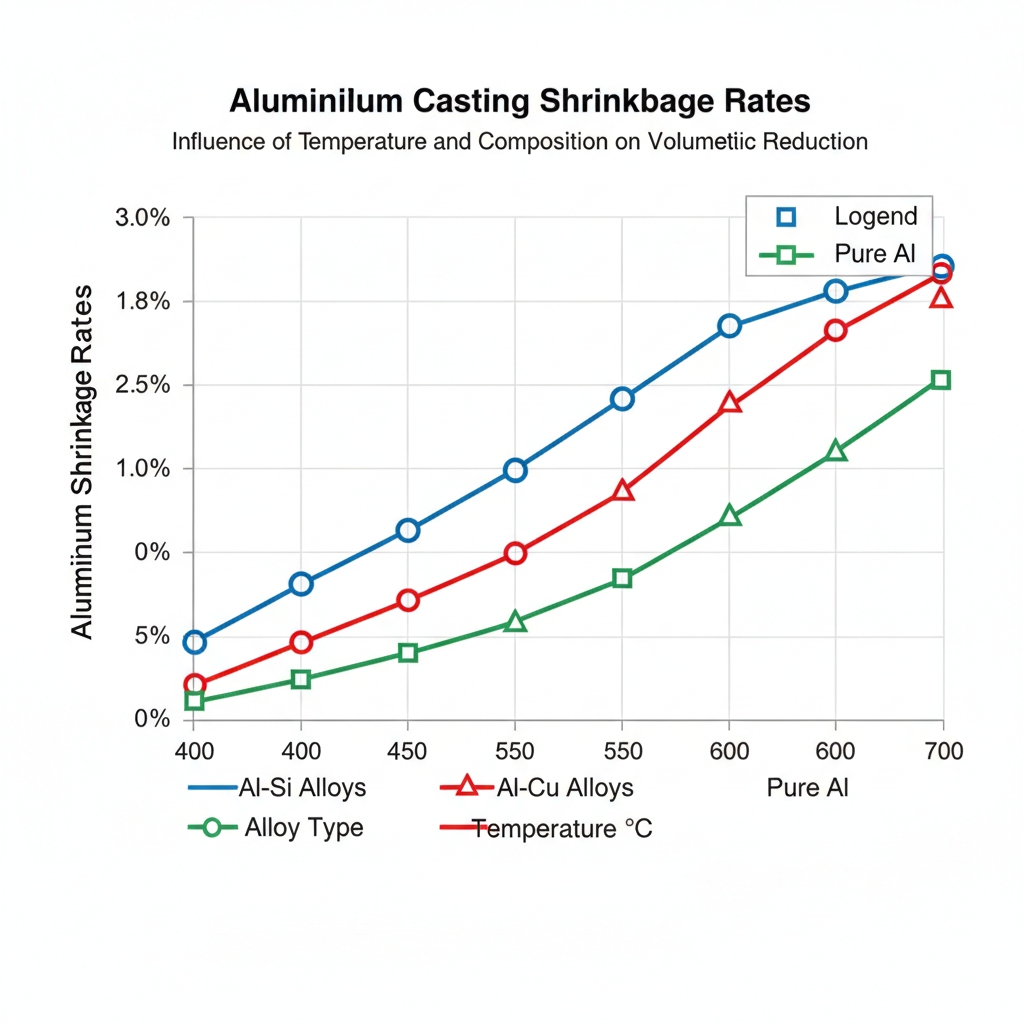
How does alloy composition impact aluminum casting shrinkage?

The chemical composition of the alloy dramatically shifts the aluminum casting shrinkage behavior, primarily due to the presence of elements like silicon. Alloys with high silicon content generally exhibit lower shrinkage rates and better fluidity, making them the preferred choice for complex sand castings where dimensional control is paramount.
You might be wondering: “Why does silicon matter so much?” Silicon expands when it solidifies, which partially offsets the natural contraction of the aluminum, effectively “filling” the voids as they form.
The role of Silicon (Si)
Silicon is the foundryman’s best friend when it comes to controlling volume.
- Mechanism: Silicon precipitates as pure particles that occupy volume.
- Benefit: Reduces external shrinkage and internal porosity.
Alloys like A356 (7% Si) are standard because this expansion capability makes the shrinkage predictable and manageable.
Comparing freezing ranges
The “freezing range” is the temperature difference between the start and end of solidification.
- Short Freezing Range (e.g., 413): Solidifies like water to ice; easier to feed.
- Long Freezing Range (e.g., 319): Passes through a slushy “mushy zone”; prone to sponge-like shrinkage.
Here is the deal: Long freezing range alloys require much larger risers to push liquid metal through the mushy dendrites.
Key Takeaway:Choosing the right alloy is as important as the mold design itself. High-silicon alloys inherently reduce the shrinkage deficit, lowering the demand on your feeding system and improving dimensional reliability.
| Alloy | Silicon % | Freezing Range | Shrinkage Tendency | |
|---|---|---|---|---|
| A356 | 7.0% | Narrow | Low | |
| 319 | 6.0% | Wide | Moderate | |
| 535 | 0.1% | Wide | High |
Analysis: Alloys with wider freezing ranges and lower silicon content will always present higher shrinkage risks and require more aggressive compensation strategies.
Which factors increase aluminum casting shrinkage risks?
Several external factors beyond alloy composition can exacerbate aluminum casting shrinkage, including pouring temperature, mold rigidity, and casting geometry. Even with a perfect pattern allowance, ignoring the thermal and mechanical constraints of the sand mold can lead to variations in dimensional accuracy that cause rejection.
Imagine this: You pour two identical parts, one at 700°C and one at 750°C. The hotter pour will shrink more because it has more liquid volume to lose before it even starts to solidify.
How pouring temperature affects volume
Superheating the metal increases fluidity but comes at a cost.
- Volume Expansion: Hotter liquid takes up more space.
- Cooling Load: The mold must absorb more heat, delaying solidification.
This extra heat keeps the riser liquid longer, which is good, but it also increases the total volume of contraction that must be fed.
Geometry and casting shape
The shape of the casting dictates how it cools and contracts.
- Hindered Contraction: Sand cores inside a box shape physically stop the metal from shrinking inward.
- Free Contraction: A simple bar or plate shrinks freely without resistance.
Complex shapes with internal cores often shrink less than the standard formula predicts because the sand is rigid.
Key Takeaway:You cannot use a single shrinkage rate for a complex part; you must consider the geometry. Thin sections cool fast, while thick junctions create hot spots that act as shrinkage reservoirs, and internal cores will physically fight the metal’s contraction.
| Factor | Condition | Effect on Shrinkage | |
|---|---|---|---|
| Pouring Temp | High Superheat | Increases Liquid Shrinkage | |
| Mold Type | Rigid Core | Hinders (Reduces) Contraction | |
| Geometry | Thick Section | Increases Porosity Risk |
Analysis: Thermal superheat and physical mold hindrance are the two external variables that most frequently invalidate standard shrinkage calculations.
How to calculate riser volume for shrinkage compensation?
To actively prevent defects caused by aluminum casting shrinkage, you must calculate the precise volume of the riser (feeder) needed to supply molten metal to the shrinking cavity. A riser that is too small will solidify before the casting, drawing metal out of the part and creating a void, while a riser that is too large wastes money.
Now, let’s look at the math: The riser must satisfy two criteria: it must contain enough liquid volume to feed the shrinkage (VfV_fVf), and it must stay liquid longer than the casting (Tf>TcT_f > T_cTf>Tc).
Using the volume formula (VfV_fVf)
The feed metal requirement is directly proportional to the volumetric shrinkage of the alloy.
- Equation: Vriser≥3×VshrinkageV_{riser} \ge 3 \times V_{shrinkage}Vriser≥3×Vshrinkage
- Context: You typically need a riser volume that is at least 3 times the volume of the shrinkage deficit to ensure the feed pipe remains open.
If your casting is 1000cc and shrinks 4% (40cc), your riser needs to provide 40cc of available liquid, but the total riser size must be much larger to maintain pressure.
Determining the shrinkage fraction
The shrinkage fraction depends on the alloy and the efficiency of your feeder.
- Efficiency: Cylindrical sand risers are only ~14% efficient.
- Implication: To provide 14cc of feed metal, you need a 100cc riser.
You can improve this by using insulating sleeves, which increase efficiency significantly.
Key Takeaway:Riser calculation is a balancing act between volume and thermal duration. A riser must be massive enough to remain liquid after the part freezes, acting as a sacrificial reservoir that takes the shrinkage defect so the part doesn’t have to.
| Component | Function | Calculation Basis | |
|---|---|---|---|
| Cavity | The Part | Part Volume () | |
| Shrinkage | Volume Loss | Vc×V_c \timesVc× Rate (e.g., 4%) | |
| Riser | Feeder | Efficiency Ratio (~15-50%) |
Analysis: Relying on guesswork for riser size guarantees scrap; mathematically verifying the feed volume is the only way to ensure internal soundness.
How do you use Chvorinov’s rule for aluminum casting?
Chvorinov’s rule is the fundamental equation used to predict the solidification time of aluminum casting shrinkage zones, ensuring that the riser freezes last. By calculating the modulus (volume-to-surface-area ratio) of both the casting and the riser, you can scientifically prove whether your gating system will function correctly.
But here is the deal: Heat leaves the casting through its surface. Therefore, a shape with a large surface area relative to its volume (like a thin plate) cools instantly, while a chunk (like a sphere) holds heat for a long time.
Calculating solidification time (TcT_cTc)
The formula states that solidification time (TTT) is proportional to the square of the modulus (MMM).
- Formula: T=C×(V/A)2T = C \times (V / A)^2T=C×(V/A)2
- Variables: VVV is Volume, AAA is Surface Area, CCC is the Mold Constant.
You don’t need to calculate absolute seconds; you just need to compare the ratios.
Using the Modulus (MMM)
The Modulus (MMM) is the most practical tool for foundry engineers.
- Rule: Mriser=1.2×McastingM_{riser} = 1.2 \times M_{casting}Mriser=1.2×Mcasting
- Logic: If the riser’s modulus is 20% larger, it will naturally stay liquid 40% longer (since 1.22=1.441.2^2 = 1.441.22=1.44).
Calculate the modulus of the thickest section of your part (the hot spot). Design your riser to have a modulus 1.2 times that value.
Key Takeaway:Chvorinov’s rule turns thermal thermodynamics into a simple geometric ratio. By ensuring your riser has a significantly higher modulus than the casting’s hot spot, you guarantee directional solidification towards the feeder.
| Geometry | Volume () | Surface Area () | Modulus () | Cooling Rate | |
|---|---|---|---|---|---|
| Thin Plate | Low | High | Low | Fast | |
| Cube | Medium | Medium | Medium | Medium | |
| Sphere | High | Low | High | Slow |
Analysis: Controlling the modulus is the primary method for directing the solidification front; heat always flows from low modulus to high modulus areas.
Can gating design control aluminum casting shrinkage?
Proper gating design does more than just fill the mold; it establishes the thermal gradients necessary to manage aluminum casting shrinkage effectively. A poorly designed gate can introduce turbulence that traps gas, or worse, creates hot spots in areas that cannot be fed, isolating liquid pockets that become shrinkage cavities.
Here is the reality: You want the metal to enter smoothly and cool progressively towards the riser. If the metal splashes or enters at the wrong velocity, you disrupt this natural thermal order.
Controlling metal flow rate
The speed at which aluminum enters the cavity matters.
- Too Slow: The metal cools prematurely (cold shuts).
- Too Fast: Turbulence creates oxides and trapped air.
A consistent, calculated flow rate ensures the mold fills evenly, keeping the temperature gradient predictable so that shrinkage happens where you planned it.
Preventing turbulence
Turbulence aerates the metal, but it also messes with thermal consistency.
- Laminar Flow: Smooth flow keeps the hottest metal moving to the riser.
- Turbulent Flow: Mixes hot and cold metal randomly.
Use tapered sprues and properly sized runners to reduce Reynolds numbers and keep the flow laminar.
Key Takeaway:Gating is your delivery system. Even if your riser is perfectly calculated, a turbulent gate that introduces air or creates random hot spots will create unpredictable shrinkage defects that no calculation can fix.
| Gating Element | Purpose | Impact on Shrinkage | |
|---|---|---|---|
| Sprue | Controls Pressure | Regulates Flow Velocity | |
| Runner | Distributes Metal | Reduces Turbulence | |
| Gate | Entry Point | Directs Hot Metal to Riser |
Analysis: A calm, calculated filling sequence is essential to maintain the thermal gradients required for directional solidification and effective feeding.
How to use chills to manage directional solidification?
When geometry prevents you from placing a riser directly over a hot spot, using chills is the most effective way to manipulate aluminum casting shrinkage. Chills are inserts made of high-conductivity metal (like steel or copper) placed inside the sand mold to rapidly extract heat from specific areas of the casting.
Imagine this: You have a heavy T-junction deep inside a casting where a riser cannot reach. Without help, that junction stays liquid and shrinks into a pore. A chill acts like a thermal sponge, sucking the heat out so that section freezes before the surrounding areas.
Internal vs. external chills
You can apply chills in two ways:
- External Chills: Placed in the mold wall, touching the surface. They are recovered after shakeout.
- Internal Chills: Placed inside the cavity and melt into the casting (same alloy). Rare in aluminum.
External chills are standard for sand casting to force cooling in thick sections.
Reducing the modulus locally
Chills work by artificially increasing the surface area’s ability to remove heat.
- Effect: Drastically reduces the effective Modulus (MMM).
- Result: The chilled section solidifies instantly, pushing the “liquid front” toward the riser.
This allows you to “push” shrinkage porosity out of critical areas and into non-critical areas or risers.
Key Takeaway:Chills are a strategic tool for altering the natural cooling physics of a casting. They allow you to force directional solidification in complex geometries where standard risering is physically impossible.
| Chill Type | Material | Thermal Conductivity | Usage | |
|---|---|---|---|---|
| Steel Chill | Carbon Steel | Moderate | General Thick Sections | |
| Copper Chill | Copper | High | Extreme Hot Spots | |
| Graphite | Graphite | Moderate/Low | Corner Refinement |
Analysis: By strategically placing chills, you effectively reprogram the cooling sequence of the casting, eliminating isolated hot spots that would otherwise cause shrinkage defects.
How to distinguish gas porosity from shrinkage defects?
Diagnosing the root cause of a defect is critical, as you must differentiate between aluminum casting shrinkage and gas porosity to apply the correct fix. While both appear as holes in the metal, their formation mechanisms—and therefore their solutions—are diametrically opposite.
But there is a catch: To the untrained eye, a hole is just a hole. However, a closer look reveals distinct signatures. Shrinkage is a vacuum defect (lack of metal), while gas is a pressure defect (trapped air).
Visual inspection of cavity characteristics
Look closely at the texture of the void.
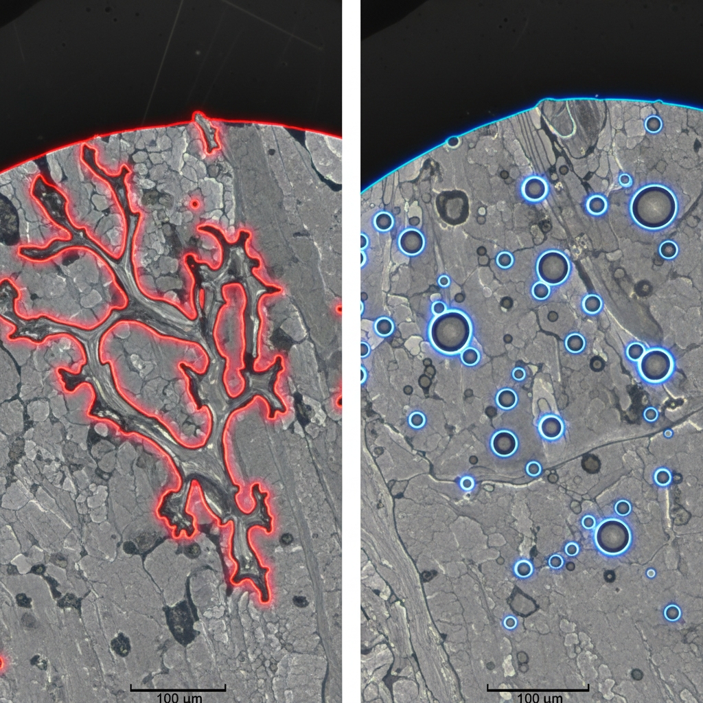
- Shrinkage Porosity: Jagged, irregular, spongy, and dendritic. It looks like a tear in the metal structure.
- Gas Porosity: Smooth, round, shiny bubbles. It looks like a bubble in soda.
If the hole is jagged and near a thick section, it’s shrinkage. If it’s round and on the surface, it’s gas.
Troubleshooting process parameters
Once identified, check the specific parameters.
- For Shrinkage: Check internal defect structure , increase riser size, lower pouring temp, or add chills.
- For Gas: Degas the melt (remove hydrogen), vent the mold, or reduce turbulence.
Applying a gas fix (venting) to a shrinkage problem will do absolutely nothing.
Key Takeaway:Correct diagnosis saves expensive iterations. Always inspect the morphology of the defect—jagged means “feed me more metal” (shrinkage), while smooth means “clean me up” (gas).
| Feature | Shrinkage Defect | Gas Porosity | |
|---|---|---|---|
| Shape | Irregular / Jagged | Round / Spherical | |
| Texture | Rough / Dendritic | Smooth / Shiny | |
| Location | Hot Spots / Thick Areas | Upper Surfaces / Random |
Analysis: Visual identification of the defect morphology is the fastest way to determine whether you have a thermal management problem (shrinkage) or a process hygiene problem (gas).
Conclusion
Mastering the calculation of aluminum casting shrinkage is the dividing line between a foundry that struggles with scrap and one that delivers precision. As we have explored, it requires a blend of mathematical rigor—applying the correct patternmaker’s allowance—and thermal engineering, ensuring your risers and chills maintain the correct directional solidification. By respecting the physics of the metal and validating your mold design with Chvorinov’s rule, you can eliminate dimensional guesswork.
Don’t let shrinkage defects eat into your margins or delay your projects. Start with the standard alloy rates, but always adjust for your specific geometry and constraints. If you need a partner who understands the intricacies of precision aluminum molding and can guarantee tight tolerances on your next production run, contact us today to discuss your project requirements with our engineering team.
FAQ Section
Q1: What is the standard shrinkage allowance for aluminum sand casting?Standard shrinkage for aluminum is typically calculated at 5/32 inch per foot (approx 1.3%). However, this is a baseline that must be adjusted based on the specific alloy composition (especially silicon content) and the rigidity of the sand mold.
Q2: Does wall thickness affect aluminum shrinkage calculations?Yes, thicker walls generally shrink more and require larger risers. Thick sections hold heat longer (higher modulus), increasing the time they remain in the “mushy” solidification phase, which increases the demand for feed metal to prevent internal porosity.
Q3: How does silicon content affect aluminum shrinkage?Silicon significantly reduces shrinkage rates. Al-Si alloys like A356 exhibit less contraction than high-strength alloys because silicon expands as it precipitates during solidification, partially offsetting the natural volume loss of the aluminum.
Q4: What is the difference between liquid and patternmaker’s shrinkage?Liquid shrinkage is the volume loss of the molten metal as it cools to the freezing point, which is handled by the riser. Patternmaker’s shrinkage is the physical contraction of the solid part as it cools to room temperature, which is handled by making the pattern larger.
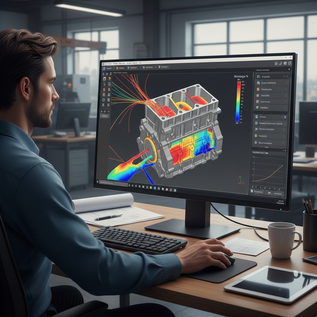
Q5: Can simulation software predict shrinkage defects accurately?Absolutely, modern solidification simulation software is highly effective. It can map thermal gradients and predict exactly where shrinkage porosity will form (“hot spots”), allowing you to adjust the riser placement or add chills in the digital design phase before pouring any metal.