Manufacturing complex aluminum components often feels like walking a tightrope between design ambition and production reality. You likely face the daily struggle of balancing intricate geometries with the soaring costs of machining and assembly, knowing that traditional methods frequently force you to compromise on one or the other. Here is the deal: If your casting tolerances drift even a fraction of a millimeter, you are looking at expensive scrap rates, delayed lead times, and a blown budget that eats directly into your bottom line. This guide explains how foam casting aluminum provides a near-net-shape solution that eliminates parting lines and ensures precision for your most difficult designs.
What Is Foam Casting Aluminum and How Did It Evolve?

Foam casting aluminum, often recognized in the industry as the lost foam process or evaporative pattern casting, represents a significant leap forward in foundry technology that dates back to its initial patenting in the late 1950s. This technique involves creating a precise pattern out of expanded polystyrene (EPS) foam, which serves as the exact replica of the metal part you intend to create. Unlike traditional methods where you must remove the pattern before pouring the metal, this process leaves the pattern inside the mold. When the molten aluminum hits the foam, the foam vaporizes instantaneously, allowing the metal to occupy the exact void left behind. We have seen this method evolve from a niche artistic technique into a dominant industrial process used for high-volume automotive components. To understand our dedication to quality in these evolving processes, you can learn more about our manufacturing standards and history.
The Origins of the Evaporative Pattern Process
You might be wondering: Why do some engineers refer to this process as manufacturing “magic” when it is simply physics at work? The answer lies in the ability of foam casting aluminum to transform a delicate, lightweight foam model into a solid, durable metal item with almost unreal precision. The process was originally patented by H.F. Shroyer in 1958, initially intended for art castings where complex shapes were required without the need for a parting line. Over the decades, the automotive industry adopted it aggressively to reduce weight. The transformation allows for the consolidation of multiple parts into a single casting, reducing the need for fasteners, welding, and assembly.
Understanding the Core Concept
The fundamental mechanism relies on the specific properties of EPS foam. It is 98% air and 2% polystyrene. When the molten metal, which is significantly hotter than the vaporization point of the foam, contacts the pattern, the foam essentially collapses and turns into gas. This gas escapes through a refractory coating into the surrounding sand. Because the sand is unbonded (it contains no resins or binders), it flows like a liquid around the pattern during the vibration stage, filling every undercut and void. This capability is what separates it from “green sand” casting, where the sand must be pressed into a hard block.
| Feature | Description | |
|---|---|---|
| Origin | Developed in the late 1950s as evaporative pattern casting. | |
| Primary Material | Expanded Polystyrene (EPS) foam is used for the pattern. | |
| Mechanism | Molten metal vaporizes the foam and replaces it. | |
| Key Benefit | Eliminates parting lines and cores. | |
| Evolution | Moved from art to heavy industrial use for weight reduction. | |
| Sand Type | Unbonded, loose dry sand. |
How Does the Foam Casting Aluminum Process Work Step-by-Step?

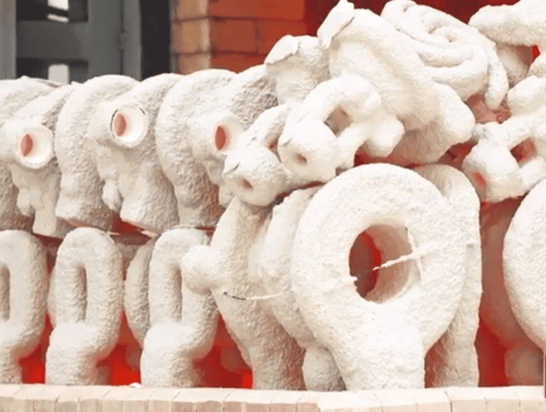
The process begins with the creation of the foam pattern itself, which is arguably the most critical step in the entire workflow. You start by injecting expanded polystyrene beads into a metal die to form the pattern sections, which are then glued together to form a complete replica of the final part, including the gating system. This assembly is often called a “cluster” if multiple parts are attached to a single sprue. The cluster is then coated in a special refractory ceramic dip. This coating is vital because it provides a rigid barrier between the foam and the sand, ensuring the liquid metal does not penetrate the surrounding molding media. While similar in precision to the investment casting process , lost foam utilizes loose sand rather than a solid ceramic shell for support.
Sand Compaction and Pouring
But here is the kicker: The actual pouring phase is where the unique nature of foam casting aluminum truly shines. Molten aluminum is poured directly onto the foam sprue. The heat from the liquid metal causes the foam to decompose and vaporize instantly. As the metal advances, it replaces the foam exactly, copying every minute detail of the surface texture and geometry. The gas produced by the vaporizing foam escapes through the permeable ceramic coating and into the sand. The flask containing the sand is vibrated vigorously prior to pouring to compact the sand into every crevice and undercut of the foam pattern, locking it firmly in place without the need for chemical binders or water.
Solidification and Finishing
Once the metal solidifies, the extraction process is remarkably simple compared to other methods. You simply tip the flask to dump out the sand and the casting. Because the sand is unbonded, it falls away easily, leaving you with a metal part that requires minimal cleaning. The sand is then cooled, screened, and recycled for the next pour. This high recyclability rate makes the process cleaner and often more environmentally friendly than chemically bonded sand processes. The casting is then sent for gate removal and any necessary heat treatment or machining.
| Step Number | Action Description | Technical Importance | |
|---|---|---|---|
| 1 | Pattern Injection | Creates the precise EPS foam replica using a metal tool. | |
| 2 | Cluster Assembly | Glues sections and gating system together to form the tree. | |
| 3 | Ceramic Coating | Prevents sand burn-in and controls gas escape rate. | |
| 4 | Sand Compaction | Vibrating loose sand locks the pattern in place without binders. | |
| 5 | Metal Pouring | Molten aluminum vaporizes foam and fills the void instantly. | |
| 6 | Shakeout | Unbonded sand is dumped out, leaving a clean casting. |
Why Is Foam Casting Aluminum Ideal for Complex Geometries?
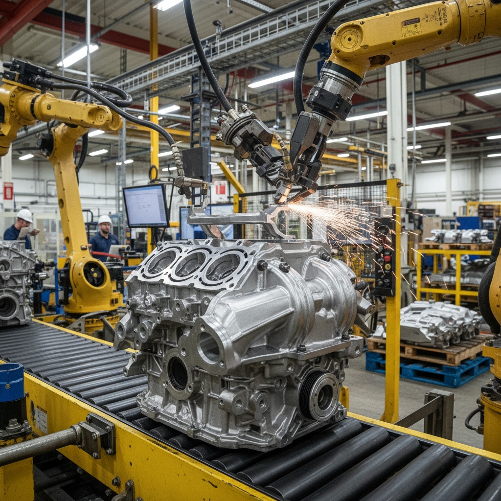
One of the primary reasons engineers turn to foam casting aluminum is its unparalleled ability to handle complex geometries that would be nightmares to produce using sand casting or die casting. Traditional methods often require draft angles—slight tapers on the vertical walls of the pattern—to ensure you can remove the pattern from the mold without damaging it. Foam casting eliminates this requirement entirely because the pattern is never removed; it is consumed. This means you can design parts with zero draft angles, complex undercuts, and intricate contours that wrap around themselves. For manufacturers, this capability opens up a world of design freedom, allowing for the creation of parts that are optimized for performance rather than limited by manufacturing constraints.
Eliminating Flash and Parting Lines
Here is the deal: When you utilize foam casting aluminum, you effectively eliminate the parting lines and flash that are ubiquitous in other casting processes. Flash is the excess metal that squeezes out between the two halves of a mold, and removing it requires time-consuming grinding and finishing. By using a single-piece foam pattern embedded in loose sand, there are no mold halves to separate, and therefore, no flash to grind off. This results in a seamless component that looks cleaner and functions better, especially in fluid-flow applications where turbulence caused by flash lines can be a detriment.
Achieving Thinner Walls and Internal Channels
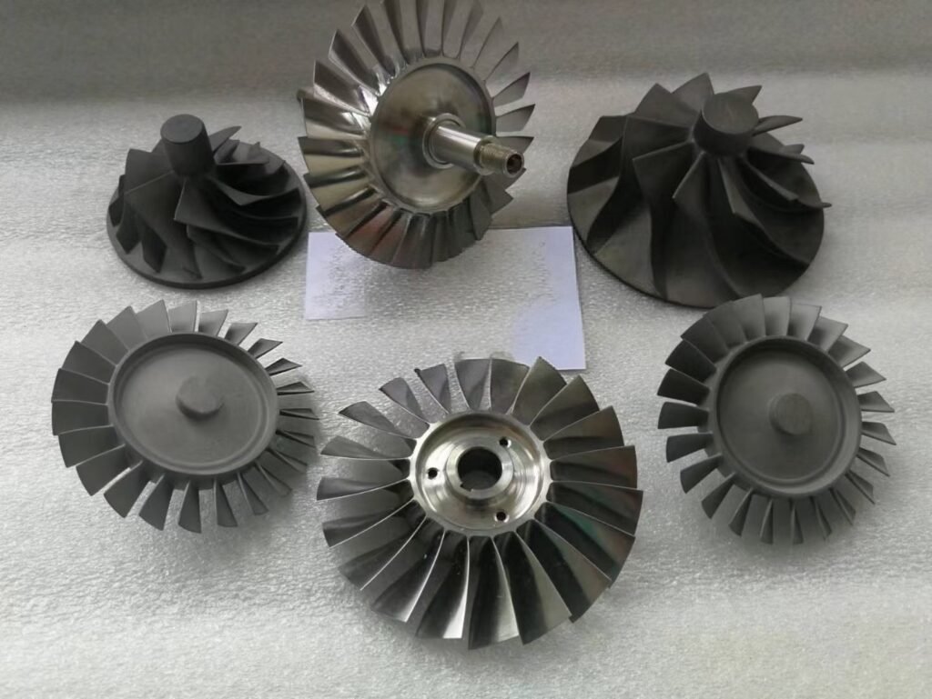
Furthermore, this process excels at creating internal channels and thin walls. In traditional casting, creating a hollow space requires a sand core, which must be formed separately and inserted into the mold. Foam casting allows you to glue foam sections together to form these internal voids upfront. This is why the process is heavily favored for manufacturing complex engine blocks, cylinder heads, and pump housings where internal fluid dynamics are critical. The lack of core prints and the ability to glue complex foam segments together allow for “impossible” shapes to be realized in a single metal pour.
| Geometry Benefit | Traditional Casting | Foam Casting Aluminum | |
|---|---|---|---|
| Parting Lines | Present, requires grinding | Eliminated completely | |
| Draft Angles | Required for pattern removal | Zero draft allowed | |
| Internal Cores | Separate sand cores needed | Built into the foam pattern | |
| Wall Thickness | Generally thicker (3-5mm min) | Allows for thinner walls (2-3mm) | |
| Design Freedom | High constraints | Near unlimited freedom |
Which Specific Alloys Are Used in Foam Casting Aluminum?
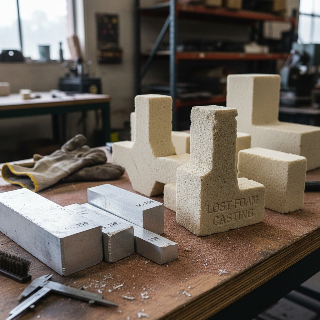
While the lost foam process can technically accommodate various metals, aluminum alloys are by far the most dominant material used due to their favorable melting points and flow characteristics. Specifically, alloys like 356 and 319 are industry standards for foam casting aluminum projects. These alloys possess excellent fluidity, which is essential because the molten metal must flow rapidly to vaporize the foam and fill the mold before it begins to solidify. The low density of aluminum also complements the process, as it reduces the hydrostatic pressure required to fill the mold, minimizing the risk of metal penetration into the sand coating. It is similar to selecting materials for investment casting , where the interaction between the melt and the mold defines the success of the part.
The Dominance of Aluminum Alloys
Aluminum 356 is perhaps the most common choice because it responds exceptionally well to heat treatment (T6), providing a high strength-to-weight ratio. Aluminum 319 is often used for engine components because of its good castability and weldability, although it is less ductile than 356. The silicon content in these alloys is critical; silicon improves fluidity and reduces shrinkage, which is vital when the metal is fighting against the back-pressure of the gas created by the vaporizing foam.
Alternative Materials Compatibility
Basically, if you are looking for versatility in material properties, the foam casting aluminum process allows for significant customization through alloying. While aluminum is king, the process is also used for cast iron and even some steel applications, though the carbon pickup from the foam can be an issue for low-carbon steels. For aluminum, you can adjust the chemical composition to enhance specific traits like corrosion resistance or thermal conductivity. Foundry experts must carefully manage the pour temperature based on the alloy; pour too cold, and the foam won’t vaporize fast enough, causing a “fold” defect. Pour too hot, and you risk burn-in.
| Alloy Type | Key Characteristics | Typical Use Cases in Foam Casting | |
|---|---|---|---|
| Aluminum 356.0 | Excellent fluidity, pressure tightness, heat treatable. | Engine blocks, pump housings, aerospace brackets. | |
| Aluminum 319.0 | Good castability, reasonable strength, cost-effective. | Cylinder heads, intake manifolds, transmission cases. | |
| Aluminum 390 | High wear resistance, high silicon. | Pistons, blocks requiring wear surfaces. | |
| Magnesium Alloys | Extremely lightweight. | specialized aerospace components (requires inhibitors in sand). |
Where Is Foam Casting Aluminum Used in Modern Industry?

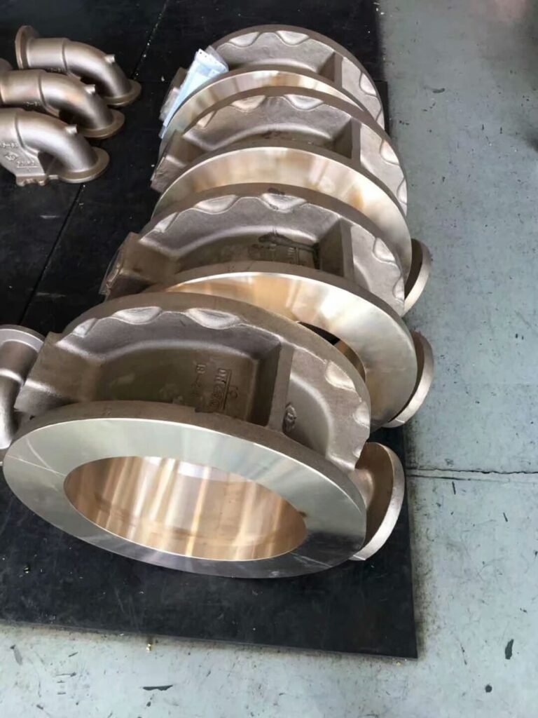
The automotive industry is the single largest consumer of parts produced via foam casting aluminum, driven by an unrelenting demand for better fuel economy through weight reduction. You will find this process responsible for millions of engine blocks, cylinder heads, and intake manifolds on the road today. By integrating multiple brackets, bosses, and flanges into a single casting, automakers reduce the part count and the weight of the engine assembly. This consolidation not only saves weight but also reduces the labor costs associated with bolting separate parts together. The marine hardware industry also utilizes this method to create complex, corrosion-resistant housings that would be too expensive to machine from solid billets.
Automotive and Engine Components
In the automotive sector, the ability to cast cooling jackets directly into the cylinder head without the risk of core shift (a common issue in sand casting) is a massive advantage. This ensures consistent wall thickness and optimal heat transfer performance. Transmission cases are another major application, where the complex oil pathways can be molded directly into the part, eliminating the need for external plumbing and potential leak points.
Aerospace and Heavy Engineering
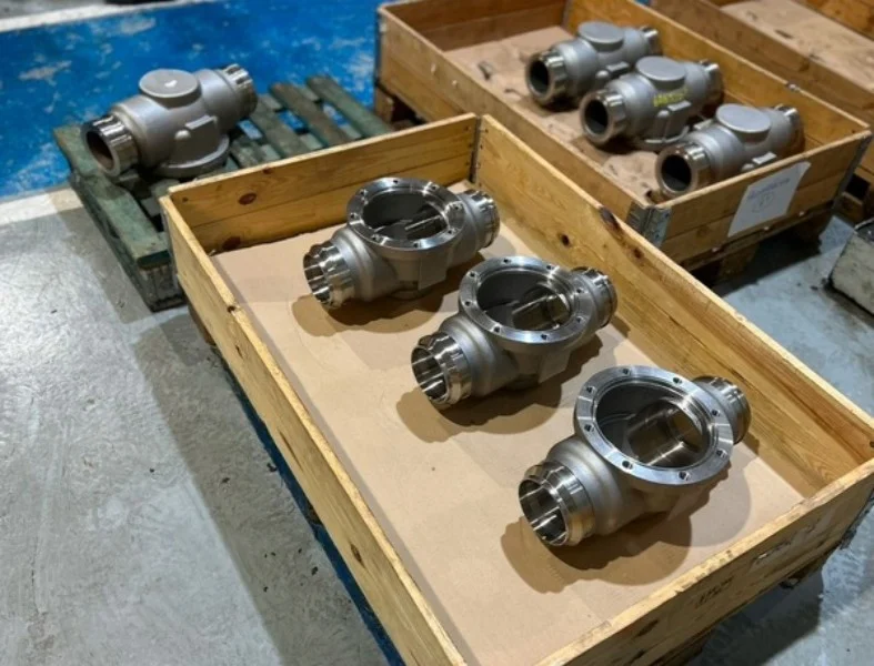
You will also see foam casting aluminum making significant inroads in the heavy equipment sectors. In hydraulic applications, manufacturers use this process to create robust valve bodies and pumps. The smooth internal passages created by the foam pattern reduce fluid turbulence, improving the efficiency of the hydraulic system. The process is also utilized in the artistic domain for casting sculptures and decorative architectural elements, where the freedom of form allows artists to create pieces that would be impossible with rigid molds.
| Industry | Common Applications | Primary Benefit | |
|---|---|---|---|
| Automotive | Engine blocks, cylinder heads | Weight reduction, part consolidation | |
| Marine | Propeller housings, lower units | Corrosion resistance, complex curves | |
| Aerospace | Structural brackets, housings | High strength-to-weight ratio | |
| Heavy Equipment | Hydraulic valves, pumps | Internal channel complexity | |
| Art/Architecture | Sculptures, decorative panels | Unlimited design freedom |
How Does Foam Casting Aluminum Compare to Sand Casting?
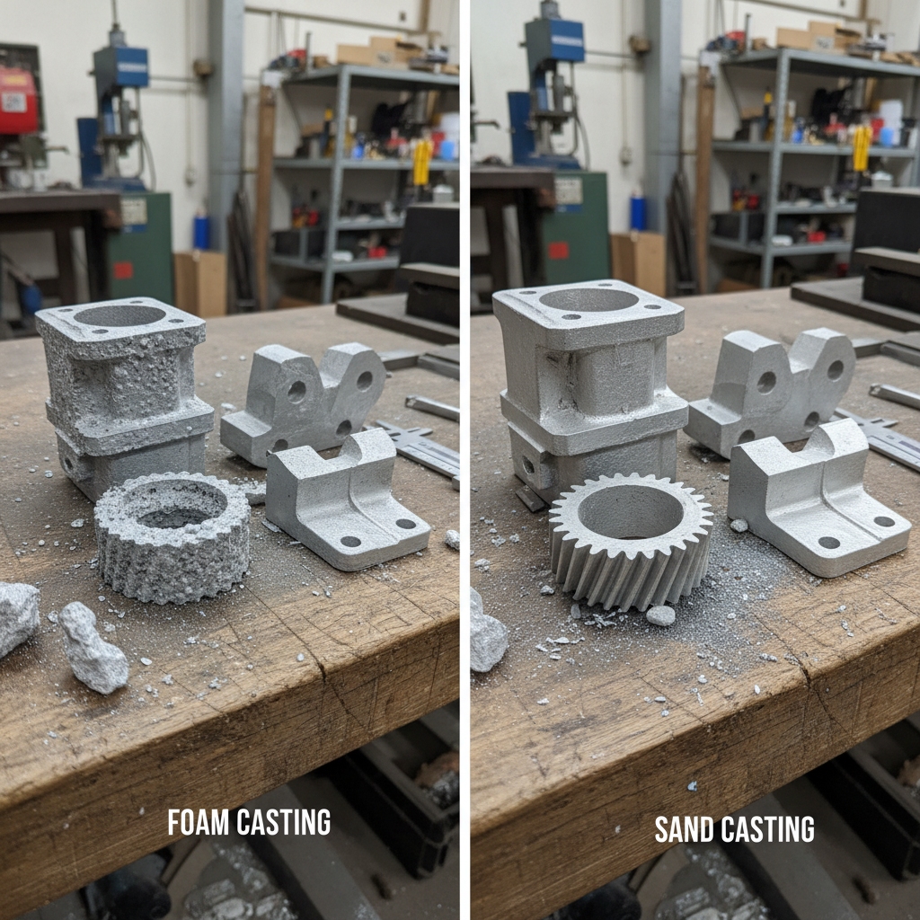
When comparing foam casting aluminum to traditional sand casting, the differences in process and output are stark. Sand casting relies on a reusable pattern to create a cavity in bonded sand (green sand or chemically bonded sand). You must construct the mold in two halves, insert cores if necessary, and then close the mold before pouring. This introduces the possibility of core shifts, parting line mismatch, and flash. In contrast, foam casting uses a single-piece pattern embedded in loose sand. This fundamental difference means that foam casting is inherently more precise regarding dimensional consistency across the parting line because there simply isn’t one. For post-processing needs, both methods may still require CNC machining for critical mating surfaces, but foam casting requires significantly less stock removal.
Analyzing the Key Differences
The most obvious difference on the factory floor is the sand. Traditional foundries are often dusty places dealing with black, bonded sand that requires heavy mulling equipment. Lost foam foundries use clean, dry silica sand that flows like water. This unbonded sand is easier to reclaim and reuse, lowering the environmental footprint. However, sand casting is generally more forgiving of large, massive parts (like giant counterweights) and has a lower entry cost for prototyping since you can make a pattern out of wood or plastic without needing a precision metal die for foam injection.
Summary Comparison
It turns out that the surface finish is another major differentiator. Sand casting often results in a rough, grainy surface texture determined by the coarseness of the sand used. Foam casting aluminum typically yields a much smoother finish because the liquid metal contacts the ceramic coating applied to the foam, rather than the sand itself. This results in a surface finish that rivals investment casting and is significantly better than standard sand casting. While sand casting is excellent for low-volume, massive components where surface finish is secondary, foam casting wins when you need high precision, complex geometry, and a surface that requires less machining.
| Metric | Foam Casting Aluminum | Traditional Sand Casting | |
|---|---|---|---|
| Molding Media | Unbonded, loose sand | Bonded (Green/Resin) sand | |
| Pattern Type | Consumable (Polystyrene) | Reusable (Wood/Metal/Plastic) | |
| Cores | Integrated into pattern | Separate sand cores required | |
| Surface Finish | Excellent (RMS 60-250) | Rough (RMS 250-500) | |
| Parting Lines | None (Seamless) | Visible, requires grinding |
What Are the Main Disadvantages of Foam Casting Aluminum?
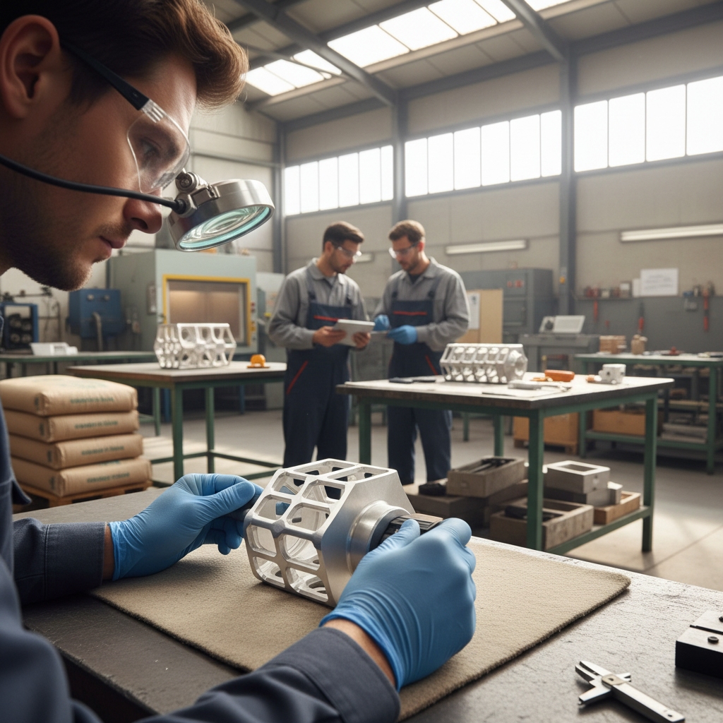
Despite its “magical” capabilities, foam casting aluminum is not without its challenges and potential pitfalls. The most significant issue you might face is porosity. Because the foam pattern creates gas as it vaporizes, that gas must escape through the coating and into the sand. If the coating is too thick or the pouring temperature is incorrect, gas can become trapped within the solidifying metal, creating voids or pockets of porosity. This is particularly problematic for pressure-tight applications where leaks cannot be tolerated. Even with high precision, verifying internal integrity often requires X-Ray testing or similar non-destructive methods to ensure no gas was trapped.
Understanding Porosity and Defects
Controlling the evaporation rate and ensuring proper permeability of the ceramic coating is a delicate science that requires strict process control. If the liquid metal advances too fast, it can surround the foam before it vaporizes, trapping the gas. If it moves too slowly, the metal might freeze before filling the mold. Carbon residue from the burnt foam can also occasionally contaminate the metal, leading to surface defects often referred to as “fold” or “carbon tracks” that might require rework or scrapping the part.
Pattern Fragility and Die Costs
Here is the reality: The fragility of the foam patterns themselves poses a logistical challenge. Before they are coated and buried in sand, the EPS patterns are lightweight and easily damaged. They must be handled with extreme care during the assembly and dipping stages to avoid dents, scratches, or breakage. Any imperfection on the foam surface will be faithfully reproduced in the aluminum casting. Additionally, the initial cost to create the metal die for injecting the foam patterns can be high. This makes the process less economically viable for very short production runs compared to sand casting or machining from solid stock.
| Disadvantage | Cause | Impact on Production | |
|---|---|---|---|
| Porosity | Trapped gas from vaporization | Leaks, structural weakness | |
| Carbon Residue | Incomplete foam combustion | Surface defects, inclusions | |
| Pattern Fragility | Delicate EPS material | Handling damage, scrap rates | |
| High Tooling Cost | Metal dies for foam injection | Barrier to low-volume runs |
How Does Foam Casting Aluminum Ensure High Surface Quality?

The secret to the superior surface finish of foam casting aluminum lies almost entirely in the refractory coating applied to the pattern. This dip coat acts as the mold face. Unlike sand casting, where the molten metal squeezes in between sand grains to create a rough texture, the ceramic shell in foam casting provides a smooth, consistent barrier. When the aluminum is poured, it creates a skin against this smooth ceramic layer. This allows for surface finishes that are typically in the range of RMS 60-250, which is considerably smoother than the RMS 250-500 typical of green sand casting. This level of finish is comparable to what is achievable in the investment casting process , making it a cost-effective alternative for parts that need good aesthetics without the high cost of wax patterns.
The Role of the Ceramic Coating
The coating must accomplish two conflicting tasks: it must be smooth enough to provide a good finish, but permeable enough to let the gas from the vaporizing foam escape rapidly. Foundries spend considerable effort formulating the “slurry” (the liquid ceramic) to balance these needs. They control the viscosity, density, and grain size of the refractory material to ensure a perfect coat. A consistent coating thickness is maintained by robotic dipping systems in modern foundries to prevent “runs” or drips that would appear as defects on the metal part.
Tolerance Capabilities
You might find that the dimensional tolerances achievable with foam casting aluminum are also tighter than traditional methods. Because the pattern is not removed from the mold, there is no mold wear or pattern degradation over time in the same way there is with sand casting plates. The unbonded sand holds the coated foam firmly, preventing wall movement during the pour. This stability allows foundries to hold tight tolerances, often reducing the amount of machining stock that needs to be added to the part. For parts requiring aesthetic appeal or smooth flow paths for fluids, this surface quality is a massive advantage.
| Feature | Foam Casting | Green Sand Casting | Benefit of Foam | |
|---|---|---|---|---|
| Surface Roughness | 60-250 RMS | 250-500 RMS | Better aesthetics, less polishing | |
| Dimensional Tolerance | +/- 0.005 inch/inch | +/- 0.030 inch/inch | Closer to net shape | |
| Mold Wear | None (consumable pattern) | High (pattern abrasion) | Consistent parts over time | |
| Machining Stock | 1.5 – 3 mm | 3 – 6 mm | Less material waste |
Is Foam Casting Aluminum the Right Choice for Heat Resistance?
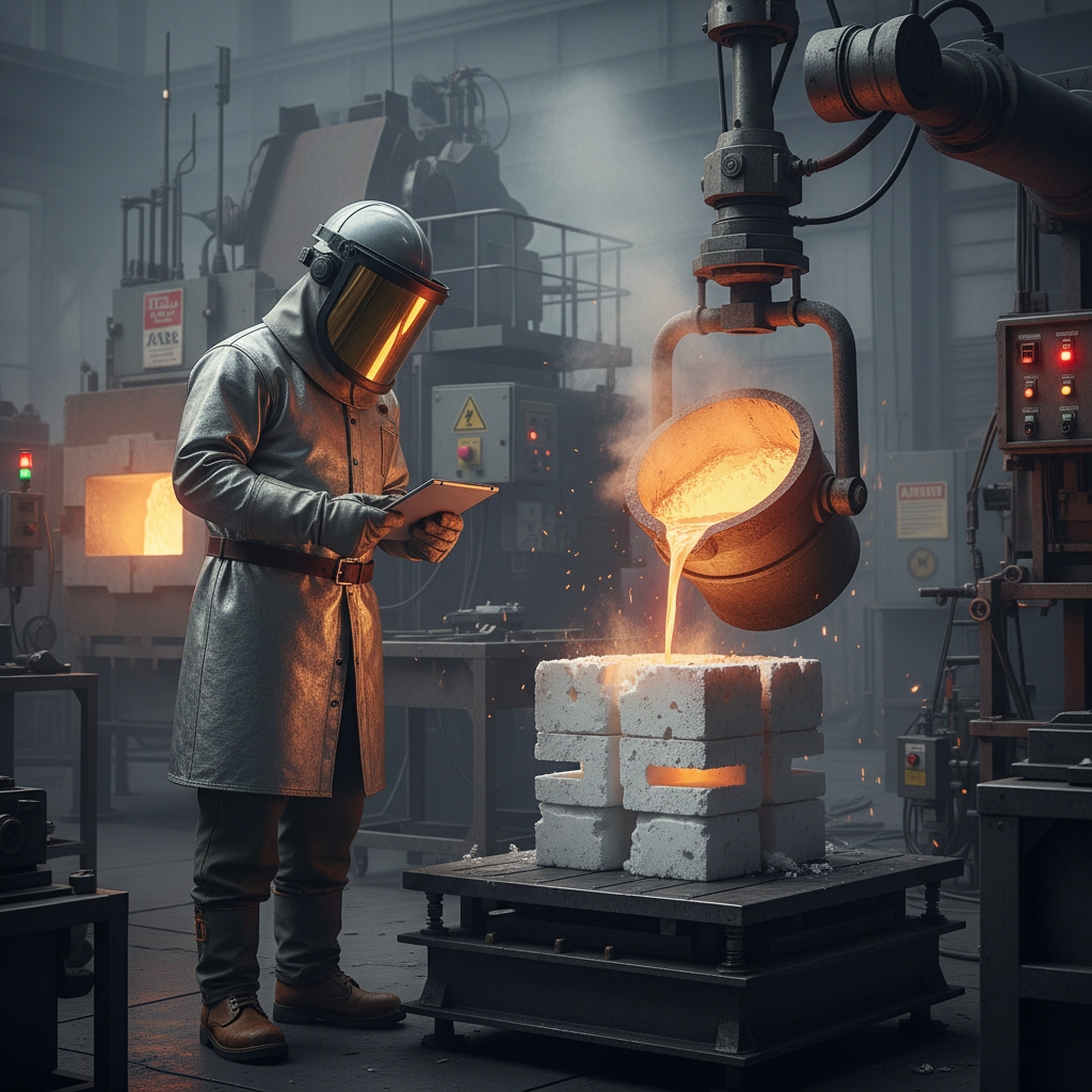
There is a common misconception that the casting process itself dictates the thermal properties of the final part. In truth, the heat resistance of a component is primarily determined by the alloy selected and the subsequent heat treatment, rather than the molding method. However, foam casting aluminum is exceptionally well-suited for creating parts that operate in high-temperature environments, such as internal combustion engines. The process allows for the integration of complex cooling jackets and water passages directly into the cylinder head or block. These cooling features are essential for managing the thermal loads generated by the engine, and foam casting is often the only way to produce such intricate internal geometries efficiently. For optimal results, specific casting heat treatment cycles are applied after the pour.
Material Properties vs. Process Capabilities
While the process facilitates the design, the alloy does the heavy lifting. Aluminum alloys like 356 and 319 retain their strength well at elevated temperatures when properly heat treated. The lost foam process ensures that these alloys can be cast with low porosity in critical areas, which improves their thermal fatigue life. Thermal fatigue occurs when a part is repeatedly heated and cooled; porous parts are prone to cracking under these cycles. By producing a denser casting (when process controls are tight), foam casting supports the alloy’s natural heat resistance.
Application in High-Temp Environments
But here is the kicker: To maximize the heat resistance of a foam cast aluminum part, you must pair the process with the correct post-casting treatments like T6 (solution heat treat and artificial aging). This significantly enhances the mechanical properties and thermal stability of the metal. The foam casting process produces parts with low residual stress because the sand is unbonded and does not restrict the metal as it shrinks during solidification. This lack of restriction means the parts are less prone to warping during the heat treatment cycle compared to parts cast in rigid dies. So, while the foam process itself doesn’t add heat resistance, it facilitates the design features and stress-free solidification that make high-temperature performance possible.
| Factor | Influence on Heat Resistance | |
|---|---|---|
| Alloy Selection | Primary driver (e.g., adding Silicon/Copper). | |
| Cooling Design | Process allows complex cooling channels. | |
| Residual Stress | Lower stress helps stability in high heat. | |
| Heat Treatment | Essential for maximizing thermal properties (e.g., T6). |
How Does Foam Casting Aluminum Impact Tooling and Production Costs?
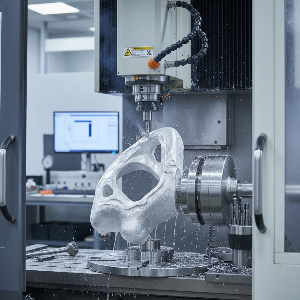
Analyzing the cost structure of foam casting aluminum requires looking at the total cost of acquisition, not just the price of the casting. It is true that the initial tooling investment is significant. You must pay for a precision-machined metal tool to inject the foam patterns. This tool is complex and expensive, often costing more than a simple sand casting matchplate. However, this upfront cost is often deceptive if you do not consider the downstream savings. Because foam casting allows you to combine several parts into one, you eliminate the purchasing, inventory, and assembly costs associated with those separate components. You also save heavily on machining costs because the part is cast near-net-shape with holes and features already in place. To understand how these costs align with our capabilities, explore our home page for an overview of our services.
Initial Investment vs. Long-Term Savings
The “break-even” point for foam casting is usually higher than sand casting but lower than high-pressure die casting. If you are making 50 parts, the tooling cost per part will be astronomical. But if you are making 5,000 or 50,000 parts, the amortization of the tool becomes negligible compared to the savings in machining and assembly labor. Additionally, the foam patterns themselves are very cheap to produce once the tool is made. The cycle time to shoot a foam pattern is fast, and multiple patterns can be glued onto a single tree, increasing the yield per pour.
Volume Considerations
Here is the deal: For medium to high-volume production, foam casting aluminum is incredibly cost-effective. The recurring costs are low because the process is highly automated, and the sand is recycled with high efficiency (often above 99%). There are no cores to manufacture and set, which is a huge labor saving in the foundry. Labor is one of the highest costs in a traditional foundry; by removing the core-setting and mold-closing steps, lost foam reduces the headcount required per ton of metal poured. Therefore, this process is a strategic financial choice for mature product lines where design stability and volume can justify the initial capital expenditure.
| Cost Factor | Foam Casting Impact | Note | |
|---|---|---|---|
| Tooling (CaPex) | High | Requires precision metal die for foam. | |
| Pattern Cost | Low | EPS beads are inexpensive. | |
| Labor Cost | Low | Automated, no core setting. | |
| Machining Cost | Significantly Reduced | Near-net-shape reduces stock removal. | |
| Assembly Cost | Eliminated/Reduced | Part consolidation integrates features. |
Conclusion
Foam casting aluminum is more than just a manufacturing technique; it is a strategic solution for overcoming the limitations of traditional metal forming. By utilizing the evaporative pattern process, you can achieve geometries that were once thought impossible, eliminate costly assembly steps, and produce near-net-shape parts with exceptional surface finishes. While it requires careful control of porosity and a higher initial tooling investment, the long-term benefits in weight reduction, part consolidation, and reduced machining make it a powerhouse option for modern industry.
As manufacturing demands continue to push for lighter, more efficient, and more complex components, the “magic” of lost foam casting will likely become the standard rather than the exception. Do not let outdated casting methods anchor your production capabilities. If you are ready to explore how this technology can optimize your supply chain, contact us today to discuss your specific requirements.
FAQs
Q1: What is the surface finish quality of foam cast aluminum? It generally offers a smooth finish (RMS 60-250) superior to sand casting, though it depends on the ceramic coating quality and sand grain fineness.
Q2: Can foam casting reduce tooling costs? It reduces machining tooling costs significantly, but the initial die cost for the foam pattern itself is higher. It pays off in volume.
Q3: What aluminum alloys are best for the lost foam process? 319 and 356 aluminum alloys are the most common due to their excellent flow characteristics and thermal properties.
Q4: Is the foam casting aluminum process environmentally friendly? Yes, largely because the sand is unbonded and can be easily recycled, and the foam evaporates cleanly with proper filtration systems.
Q5: How do I prevent porosity in foam casting aluminum parts? Precise control of the pouring temperature, using high-quality foam with consistent density, and ensuring the ceramic coating is perfectly permeable for gas escape.


