Learn 3D printing threads with precisionvast for strong durable joints using optimized designs slicer settings and metal inserts.
Anatomy of a 3D Printed Thread
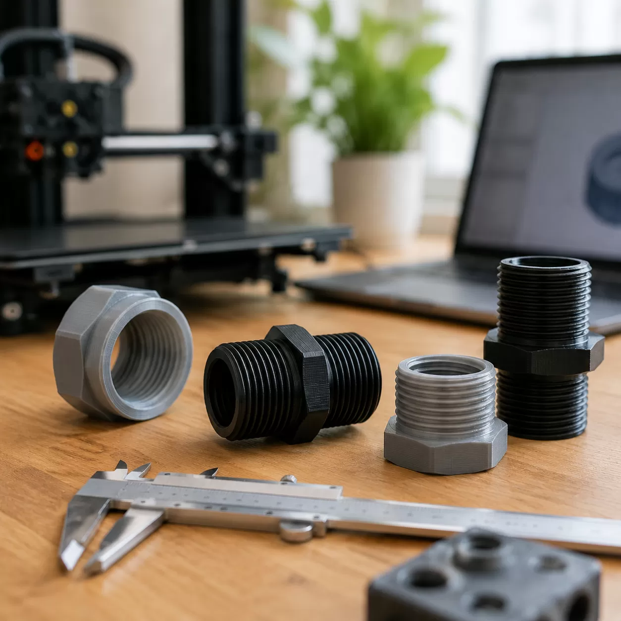
When designing 3D printed threads, understanding the basic geometry is the difference between a smooth mechanical joint and a stripped piece of plastic. Every thread relies on specific geometric definitions to function correctly.
- Major Diameter: The largest diameter of the thread, measured from crest to crest.
- Minor Diameter (Root Diameter): The smallest diameter, measured from the innermost valleys (roots).
- Thread Pitch: The linear distance from the peak of one thread to the next.
- Lead: The distance a screw travels axially in one complete 360-degree rotation.
- Crest and Root: The flat or rounded top (crest) and bottom (root) shapes of the thread profile.
Metric Thread 3D Model vs. Imperial UTS
Choosing the right thread standard depends on your project requirements. Standard fasteners generally fall into two main categories:
| Thread Standard | Common Sizes for 3D Printing | Best Use Case |
|---|---|---|
| ISO Metric (M) | M3, M4, M5, M6 3D print bolts, M8 | Global standard, excellent for small to medium functional prints. |
| Unified Thread Standard (UTS) | 4-40, 1/4-20 | Imperial standard, ideal for US-based hardware compatibility. |
Profile Variations for Additive Manufacturing
Standard sharp triangular profiles (like standard 60-degree V-threads) are difficult to replicate cleanly on 3D printers due to strict overhang thread design limitations. Modifying the thread profile shape helps ensure clean prints without drooping plastic.
- Triangular Profiles: Common for standard fasteners, but the sharp peaks often fail to print cleanly on FDM machines without micro-sagging.
- Trapezoidal Profiles (ACME): Feature flat crests and roots with steeper angles, significantly improving horizontal strength and reducing print defects.
- Semi-Circular Profiles: The most reliable choice for custom high-strength printed screws. The rounded geometry eliminates steep overhangs completely, allowing the printer to lay down smooth, continuous layers.
Engineering Design Guides and CAD Modeling Tolerances
When designing 3D printed fasteners, getting your CAD thread clearance right is the difference between a perfect fit and a fused chunk of plastic. Parametric modeling software like Fusion 360 allows you to model functional metric thread 3D models or imperial profiles, but you cannot rely on default global thread standards. 3D printers extrude material that naturally swells, requiring manual clearance adjustments built directly into your digital design.
Horizontal vs. Vertical Tolerance Margins
Achieving smooth mechanical joints in 3D printing requires accounting for the material shrinkage factor of different polymers. For instance, high-temperature filaments shrink significantly more than standard PLA, which mirrors the dimensional changes seen when engineering cast metals.
Use this quick tolerance reference table for modeling FDM internal threads and resin equivalents:
| Printer Technology | Recommended Thread Clearance | Key Material Focus |
|---|---|---|
| FDM / FFF | 0.1mm to 0.2mm | PLA, ABS, PETG, Nylon |
| SLA / Resin | 0.05mm | Thermoset Tough/Engineering Resins |
Managing Overhang Thread Design Without Supports
To print clean internal and external threads, you must eliminate the need for temporary support material inside the thread tracks. Support removal ruins the pitch geometry.
- Keep thread slope angles under the critical 30 to 45-degree limit relative to the vertical print bed.
- Utilize modified trapezoidal or semi-circular thread profiles instead of sharp 60-degree V-threads.
- Orient your parts vertically so the thread profile steps up gradually layer by layer, maximizing self-supporting geometry.
Advanced Slicing Settings for Maximum Thread Integrity
Getting clean, functional 3d printing threads relies heavily on your slicer configuration. Standard print settings often round off the sharp peaks and valleys required for a tight mechanical fit. To achieve maximum strength and precision, you must tune your layer resolution, perimeter thickness, and material flow.
Optimal Layer Height and Resolution
For crisp FDM internal threads, generic 0.2mm layer heights simply will not cut it. Lower layer heights provide the staircase resolution needed to accurately recreate the slope of a metric thread 3D model.
- Recommended Range: 0.12mm to 0.16mm layer height.
- Why it matters: Thinner layers reduce the stepping effect on the thread flanks, ensuring smoother engagement and preventing high-strength printed screws from binding or stripping during assembly.
Wall Thickness and Shell Optimization
Never rely on infill to support the load of a mechanical joint. The strength of your threads comes entirely from the outer perimeters.
- Perimeter Count: Set a minimum of 4 perimeters (shells).
- Total Wall Thickness: Target at least 2.0mm total wall thickness around the threaded hole.
- This optimization ensures that when you torque down a bolt, the forces are distributed across solid plastic boundaries rather than tearing into hollow infill structures.
Infill and Flow Rate Calibration
Over-extrusion is the ultimate enemy of functional 3d printing threads. If your printer pushes out too much material, it will bottleneck the internal thread pitch and shrink the minor diameter.
| Slicer Setting | Target Value | Impact on Threads |
|---|---|---|
| Infill Density | 30% to 50% | Provides a rigid internal backing for the solid walls. |
| Infill Pattern | Gyroid or Grid | Offers equal isotropic support under rotational torque. |
| Flow Rate (Extrusion Multiplier) | 93% to 97% (Calibrated) | Prevents plastic blobbing in the tight roots of the threads. |
Pro-Tip: Always run a quick single-wall extrusion test to calibrate your flow rate before printing complex polymer fastening solutions. A perfectly calibrated flow rate ensures that male and female threads match your CAD dimensions exactly without binding.
For more technical guides on optimizing your manufacturing setups, check out our insights on the latest production updates on the Precisionvast blog.
Metal Reinforcements: The Precisionvast Threaded Insert Suite
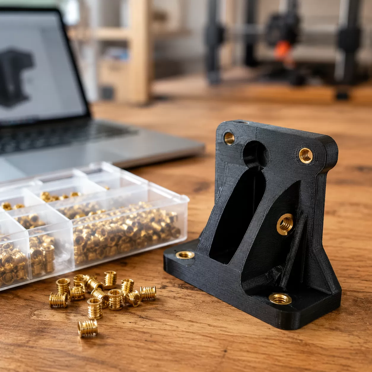
When your 3D printed threads need to handle repetitive assembly or heavy structural loads, plastic-on-plastic connections simply won’t cut it. I rely on metal reinforcement solutions to ensure long-term reliability for my projects. Our threaded brass inserts are engineered for seamless integration into FDM, SLA, and SLS parts, providing the robust mechanical joints in 3D printing that demanding industrial applications require.
- Heat-Set Inserts for FDM: For common thermoplastics like PLA, ABS, PETG, and Nylon, heat-set inserts for 3D printing are the gold standard. By using a temperature-controlled soldering tip, you can heat the insert until it melts the surrounding plastic just enough to seat it flush. Once the plastic cools, it creates a locked-in, high-strength bond.
- Press-Fit and Self-Tapping: For thermoset resin (SLA) or composite (SLS) components, we utilize specialized press-fit or self-tapping metal inserts. Since these materials do not reflow like thermoplastics, these inserts rely on high-precision tolerances to maintain structural integrity.
- Performance Engineering: The effectiveness of any polymer fastening solution hinges on the knurling pattern and material choice. Proper knurling ensures the insert resists both pull-out and torque. When selecting these hardware components, opting for essential alloys for maximum high-temperature durability ensures your assemblies hold up under thermal expansion without failing.
Whether you are using knurled nut inserts for a quick prototype or a permanent chassis mount, using the correct insert geometry minimizes stress risers and prevents the underlying plastic from cracking or stripping.
Post-Processing and Mechanical Refinement for 3D Printing Threads
Sometimes, getting perfect 3D printing threads straight off the build plate requires a little extra refinement. If your layer lines are tight or minor tolerances are slightly off, manual plastic thread tapping is the most reliable fallback. Running a precision tap down an internal thread or using a die set on external 3D printed fasteners easily clears out stray blobs and cleans up printed boundaries for a smooth, true fit.
Beyond mechanical cleanup, managing structural integrity at the polymer level prevents premature stripping. For demanding applications, thermal annealing provides excellent stress relief. By baking engineering thermoplastics at controlled temperatures, you enhance polymer crystallinity, which significantly boosts structural yield strength.
Additionally, chemical vapor smoothing works wonders on materials like ABS or ASA. This process melts away micro-stress risers along the layer lines, smoothing out the thread profile and drastically reducing friction during assembly. For more advanced manufacturing insights, you can explore the PrecisionVast blog to see how post-processing optimizes custom components.
Post-Processing Methods Comparison
| Refinement Method | Target Materials | Primary Benefit | Best For |
|---|---|---|---|
| Manual Tapping & Chasing | PLA, PETG, ABS, Nylon | Cleans thread geometry & removes print artifacts | Restoring tight CAD thread clearance |
| Thermal Annealing | PLA, PETG, Engineering Polymers | Boosts crystallinity & structural yield strength | High-strength printed screws |
| Chemical Vapor Smoothing | ABS, ASA | Eliminates layer lines & micro-stress risers | Reducing friction in mechanical joints |
Real-World Applications of 3D Printing Threads
Integrating durable 3D printing threads into functional parts is a game-changer across multiple US manufacturing sectors. By combining adaptive additive manufacturing with rugged polymer fastening solutions, our partners drastically cut down assembly times while maximizing structural integrity.
Here is how different industries utilize these advanced fastening methods:
Industrial Automation and Robotics
Modern robotics demand rapid deployment and reliable mechanical joints. Engineers utilize our precisionvast fastening arrays directly within customized end-of-arm tooling and sensor brackets.
- High-Strength Connections: Utilizing heavy-duty M6 3D print bolts alongside reinforced internal threads allows robotic arms to withstand continuous vibrational stress.
- Rapid Customization: Automated production lines use these integrated threads to quickly swap out modular components without redesigning entire assemblies.
Aerospace Prototyping
Weight reduction is everything in aerospace development. When engineering lightweight functional housings, components must endure frequent assembly and disassembly cycles during wind tunnel and fitment testing.
- Material Efficiency: Using precise overhang thread design principles eliminates the need for heavy, solid metal blocks, keeping drones and UAV prototypes exceptionally light.
- Wear Resistance: To prevent the plastic from wearing down after repeated setups, engineers embed robust heat-resistant metals into the printed housings, ensuring the hardware never strips during critical test flights.
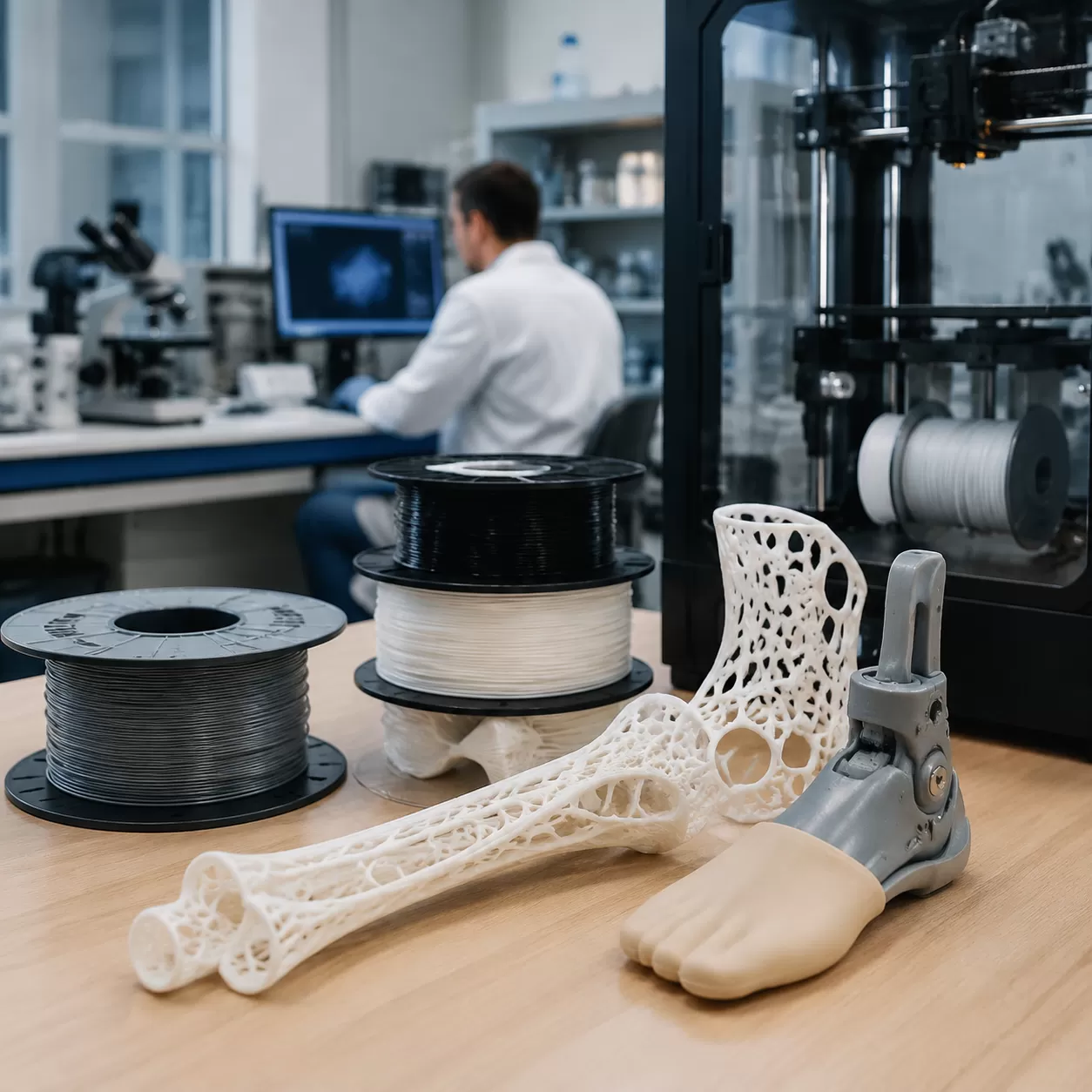
Medical Devices
Custom healthcare solutions require absolute precision and biocompatibility. We see a massive demand for tailored enclosures that protect sensitive electronic testing arrays.
- Secured Internal Chassis: Printed enclosures utilize reliable metal-on-metal internal chassis mounts to keep delicate sensors locked in place.
- Sterilization Ready: By combining high-temperature biocompatible polymers with precise CAD thread clearance, these medical devices can go through standard sanitization cycles without losing their structural torque limits.
Frequently Asked Questions About 3D Printing Threads
How do I stop 3D printed threads from stripping?
To prevent plastic threads from stripping, increase your wall thickness to at least 4 perimeters so the bolt grips solid plastic instead of hollow infill. Printing at a slightly higher temperature also improves layer adhesion, which keeps the thread crests from shearing off under load. For heavy-duty mechanical joints in 3D printing, upgrading to metal inserts is the best way to handle high torque.
What is the best layer height for printing 3D threads?
The sweet spot for printing reliable 3D printed fasteners is a layer height between 0.12mm and 0.16mm. Lower layer heights capture the steep slopes of a metric thread 3D model with much higher fidelity. This reduces the staircase effect on the thread profile, resulting in smoother engagement and less friction when screwing parts together.
Should I use 3D printed threads or brass heat-set inserts?
- Use 3D printed threads for low-load applications, large thread sizes (M8 and above), or temporary prototypes that won’t be taken apart frequently.
- Use threaded brass inserts for high-stress parts, small thread sizes (M3 to M5), and components requiring frequent assembly and disassembly.
For projects requiring maximum longevity, our team at Precisionvast always recommends integrating knurled nut inserts into your design. To see how we approach high-durability manufacturing configurations across different production methods, check out our insights on the advantages and disadvantages of high-pressure die casting.
How much tolerance clearance should I add to my CAD thread model?
For standard FDM internal threads, add a horizontal CAD thread clearance of 0.15mm to 0.2mm to your model to account for plastic shrinkage and extrusion swell. If you are using a high-precision SLA resin printer, you can tighten that clearance down to 0.05mm.
| Printer Type | Recommended Thread Clearance | Optimal Layer Height |
|---|---|---|
| FDM (PLA/PETG/Nylon) | 0.15mm – 0.20mm | 0.12mm – 0.16mm |
| SLA (Resin) | 0.05mm – 0.10mm | 0.05mm |
Can you tap threads directly into a 3D printed plastic part?
Yes, plastic thread tapping works exceptionally well if you plan ahead. Print the hole completely solid by increasing your perimeter count, making sure the inner diameter matches the specific drill chart size for your tap. Run a standard metal tap into the printed hole slowly, backing out frequently to clear out plastic shavings and prevent the material from tearing.