Surface finish callout guide for engineers covering surface roughness symbols Ra Rz charts lay direction and CNC machining specs.
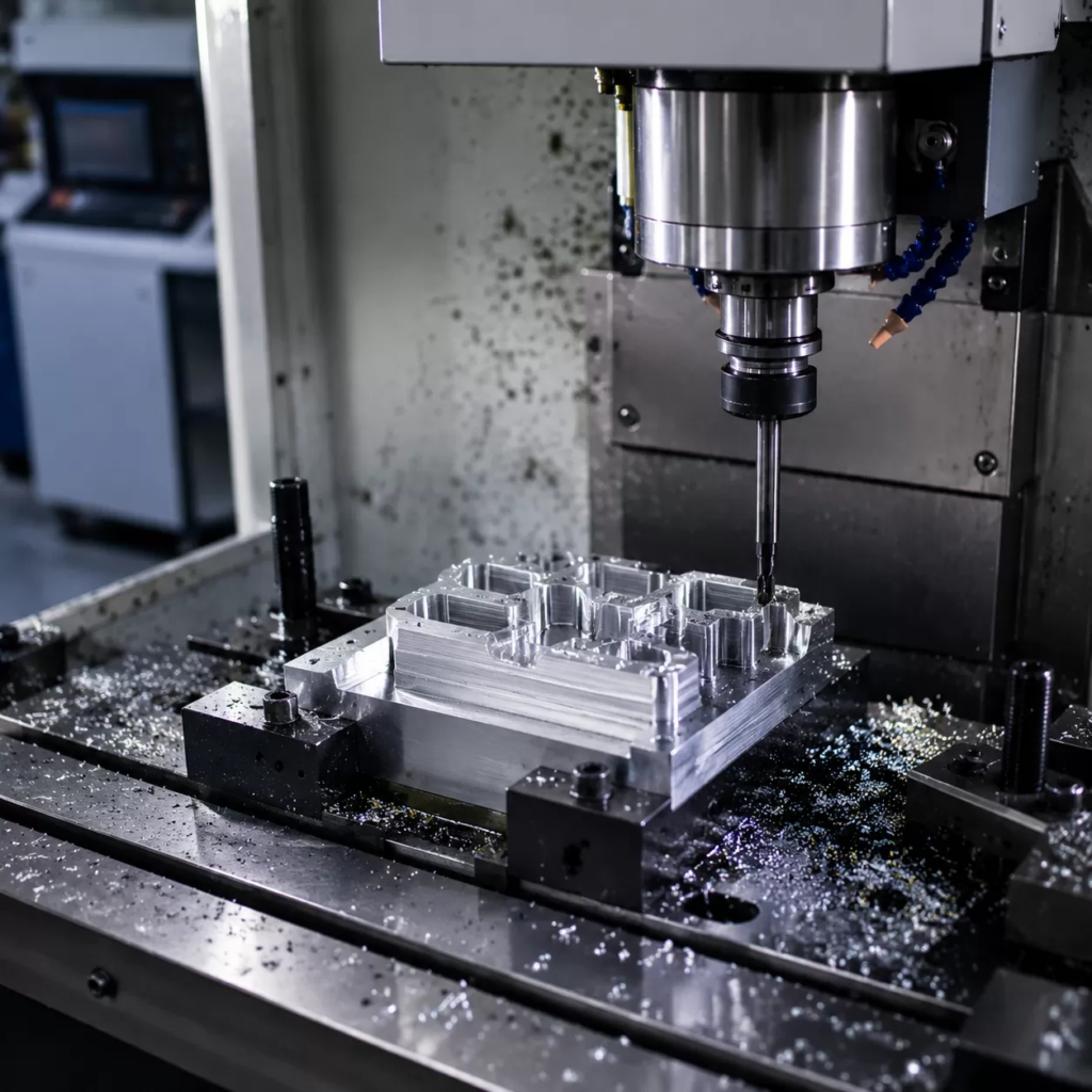
How do you ensure a machine shop delivers the exact texture your design demands? It all comes down to mastering the surface finish callout. If you just throw a generic note on your engineering drawing, you risk receiving parts that are either functionally useless or needlessly expensive. We rely on the standard geometric dimensioning and tolerancing (GD&T) surface control symbols to communicate explicit texture limits directly on our production prints.
The 60-Degree Check-Mark Symbol
The backbone of any surface finish specification is the basic check-mark symbol. This symbol features a short leg on the left and a longer leg on the right, drawn at a strict 60-degree angle. By itself, this basic symbol simply dictates that the surface requires control, but it leaves the manufacturing method open.
To specify how the factory must achieve that finish, we modify the check-mark with explicit material removal rules:
- Basic Symbol (Open Triangle): Specifies surface texture control is required, but material removal is optional. The shop can machine it, cast it, or leave it stock.
- Material Removal Required (Closed Triangle): A horizontal bar caps the check-mark. This explicitly mandates a machining operation (milling, turning, grinding) to cut away material and achieve the texture.
- Material Removal Prohibited (Circle Insert): A circle is nestled in the vertex. This strictly forbids any material removal, forcing the shop to maintain the finish from the raw stock, casting, or forging process.
Mapping Auxiliary Specifications
When a design requires advanced control, a standalone symbol isn’t enough. We use standardized callout positions around the check-mark to inject precise manufacturing data. Both the ASME B46.1 and ISO 1302 surface texture standards map distinct zones to prevent drawing clutter while packing in dense technical data.
| Position Zone | Callout Specification Meaning | Typical Engineering Example |
|---|---|---|
| Position A | First Roughness Value (Typically Ra) | 3.2 µm (125 µin) max allowable roughness |
| Position B | Production Method or Treatment | Ground, Lapped, Anodized, or Chrome Plated |
| Position C | Cutoff Wavelength or Evaluation Length | 0.8 mm default sampling length |
| Position D | Lay Direction Symbol | Parallel (∥), Perpendicular (⊥), or Cross (X) |
| Position E | Machining Allowance (Material to remove) | 2.0 mm stock removal allowance |
By decoding positions A through E, our production drawings seamlessly instruct inspectors and CNC programmers exactly which parameters to measure, which direction the tool marks must run, and how much raw material to leave on the blank.
Core Surface Roughness Parameters Explained
When specifying a surface finish callout on your engineering drawings, relying on a single default texture callout can lead to failed parts or skyrocketing production costs. Different manufacturing applications require different surface roughness control symbols to function properly in the field.
Here are the three primary parameters used in United States manufacturing hubs to define surface quality.
- Ra (Arithmetic Average Roughness): This is the undisputed industry standard for general machining surface texture charts. It measures the average deviation of a profile from the mean line. It is ideal for checking general fitment and cosmetic surfaces, but it can occasionally miss isolated deep scratches.
- Rz (Maximum Height of Profile): This parameter measures the distance between the single highest peak and the lowest valley within a sampling length. It is a critical engineering drawing texture callout for dynamic fluid seals, high-pressure gaskets, and heavy O-ring applications where a single deep scratch could cause a fluid leak.
- Rq (RMS Roughness): Root Mean Square roughness is a statistical measure that is more sensitive to occasional peaks and valleys than Ra. We specify Rq primarily for high-precision optical components, mirrors, and advanced bearing surfaces.
Metric vs. Imperial Conversion Matrix
United States machine shops frequently switch between metric micrometers ($mu$m) and imperial micro-inches ($mu$in). When prepping your drawings, you can use this conversion matrix to ensure your production drawing texture indicators match standard workshop capabilities.
| Ra Value (Micrometers – $mu$m) | Ra Value (Micro-inches – $mu$in) | Common Manufacturing Process | Cost Impact |
|---|---|---|---|
| 6.3 $mu$m | 250 $mu$in | Rough Milling / Heavy Turning | Low / Standard |
| 3.2 $mu$m | 125 $mu$in | Standard CNC Milling | Baseline |
| 1.6 $mu$m | 63 $mu$in | Finish Machining | Moderate |
| 0.8 $mu$m | 32 $mu$in | Precision Machining / Grinding | High |
| 0.4 $mu$m | 16 $mu$in | Fine Grinding / Honing | Very High |
| 0.2 $mu$m | 8 $mu$in | Lapping / Superfinishing | Extremely High |
Pro Tip: Post-processing will alter these values. If your design requires secondary operations, make sure to review our guide on investment casting surface treatments to understand how coatings, anodizing, and blasting change your final surface finish callout measurements before the parts ship to assembly.
Lay Direction Symbols & Mechanical Implications
When specifying a surface finish callout, defining the dominant pattern of the surface texture—known as the lay—is critical for governing friction, wear, and fluid sealing. The direction of the tool marks left behind by manufacturing processes directly impacts how mating parts interact under mechanical loads.
Parallel ($parallel$) and Perpendicular ($perp$) Pattern Orientation
The orientation of your surface texture can make or break a mechanical assembly.
- Parallel Lay ($parallel$): Tool marks run parallel to the line representing the surface in the drawing. This orientation is highly effective for reducing friction in linear motion systems, such as sliding ways, where the mating component moves along the direction of the grooves.
- Perpendicular Lay ($perp$): Tool marks run perpendicular to the surface line. This pattern is commonly used to retain lubricants or to create a deliberate braking action, though it can accelerate initial component wear if not carefully managed.
Crossed (X) and Multidirectional (M) Textures for Multi-Axis Movement
For components undergoing complex or multi-directional stress, simple linear patterns often fall short.
- Crossed Lay (X): This symbol indicates tool marks that cross in two distinct directions, creating a cross-hatch pattern. It is the gold standard for internal combustion engine cylinder bores, as the intersecting grooves hold oil perfectly while supporting the reciprocating motion of piston rings.
- Multidirectional Lay (M): This callout signifies a surface with no dominant direction, typically producing a random, matte texture. It is ideal for multi-axis thrust bearings, generalized contact plates, and surfaces slated for specialized coatings. For components operating under extreme thermal stress, combining an multidirectional lay with robust material choices like high-temperature alloys ensures reliable performance and structural integrity.
Concentric (C) and Radial (R) Lathe Facing Patterns
Rotational parts require specialized lay designations to ensure proper sealing and fitment during final assembly.
- Concentric Lay (C): Tool marks form concentric circles around a central point, a pattern typical of a part spun on a lathe or grinding spindle. This lay is mandatory for high-pressure O-ring grooves and face seals, as fluid cannot easily travel across the continuous circular ridges.
- Radial Lay (R): Tool marks radiate outward from a central point like spokes on a wheel. This texture is often found on friction discs, clutches, and specific rotating contact faces where radial fluid dispersion or uniform friction is required.
Manufacturing Process Capabilities & Cost Optimization
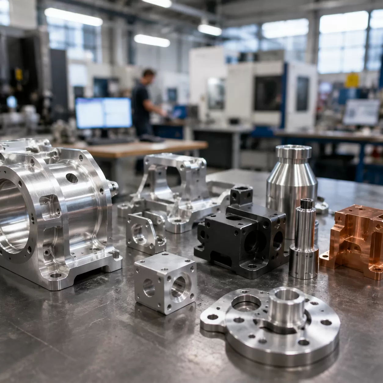
Choosing the right surface finish callout for your production drawings directly impacts both your part’s performance and its production cost. Every manufacturing process has an inherent limit to the surface quality it can achieve efficiently. Pushing a process beyond its standard capability drastically spikes cycle times and scrap rates.
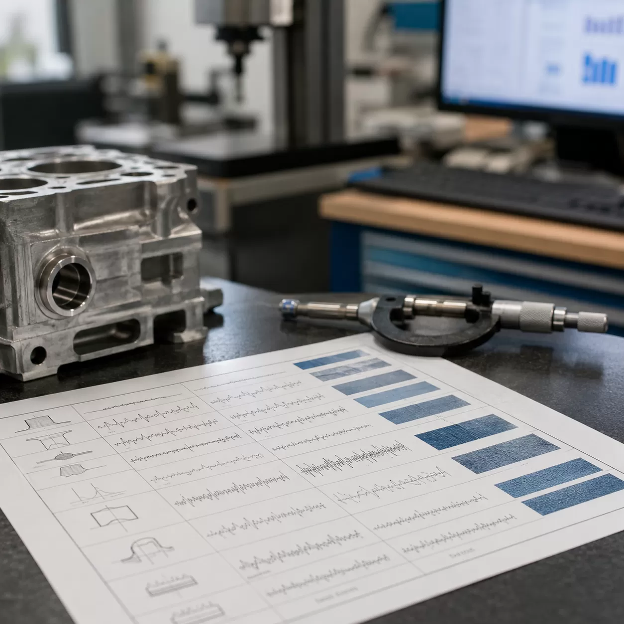
Surface Finish Capabilities by Process Chart
The table below outlines the typical surface roughness ranges ($R_a$) achievable by common manufacturing methods.
| Manufacturing Process | Standard Surface Finish ($R_a$ µm) | Standard Surface Finish ($R_a$ µin) | Cost Premium for Higher Quality |
|---|---|---|---|
| Sand Casting | 12.5 – 25.0 | 500 – 1000 | Low |
| Standard CNC Milling | 1.6 – 3.2 | 63 – 125 | Baseline |
| Precision CNC Turning | 0.8 – 1.6 | 32 – 63 | Moderate |
| Precision Grinding | 0.2 – 0.8 | 8 – 32 | High |
| Honing / Lapping | 0.05 – 0.2 | 2 – 8 | Very High |
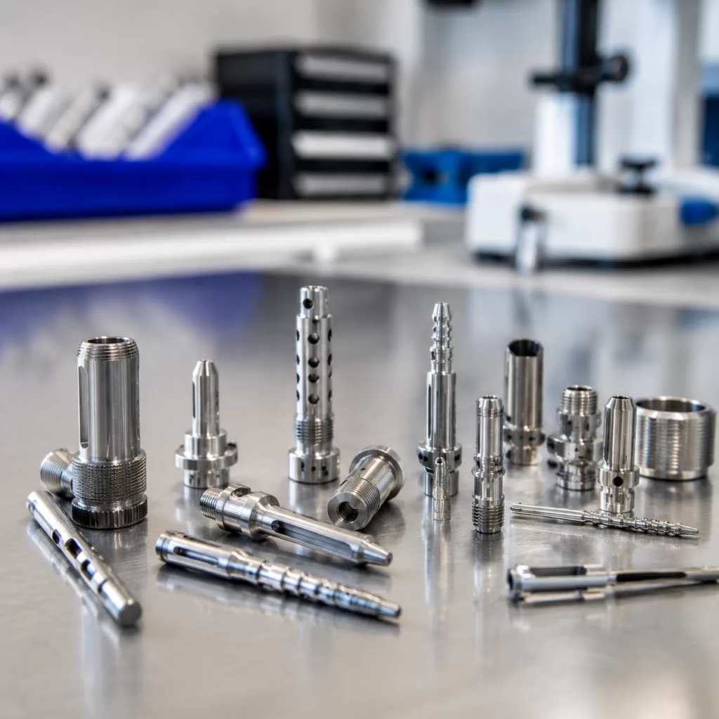
Standard CNC Milling/Turning vs. Precision Grinding & Honing
For most standard industrial applications, standard CNC milling and turning offer the most economical path. A standard CNC surface roughness callout of $1.6text{ }mutext{m}$ ($63text{ }mutext{in}$) is easily achievable with modern tooling and regular feeds. If you are machining challenging materials, understanding how specific grades behave can help you optimize your machining strategy; for example, look at how material properties influence tool wear and finish when comparing 304 vs 316 stainless steel for CNC machining.
When a drawing specifies an ultra-smooth precision machining surface finish specification below $0.4text{ }mutext{m}$ ($16text{ }mutext{in}$), standard cutting tools reach their physical limits. At this stage, secondary operations like precision grinding, honing, or lapping become mandatory. These processes do not remove bulk material efficiently; instead, they slowly abrade the high points of the surface profile to meet strict engineering tolerances, which adds extra steps to your production line.
The Cost-Tolerance Curve: Balancing Finish Against Cycle Time
Achieving a tighter surface finish requires a strict tradeoff with machine cycle time. To drop from a $3.2text{ }mutext{m}$ ($125text{ }mutext{in}$) finish down to a $0.8text{ }mutext{m}$ ($32text{ }mutext{in}$) finish on a mill, the operator must reduce the feed rate and use smaller stepovers. This adjustment exponentially increases the time the tool spends cutting the metal.
- Exponential Cost Growth: Demanding a finish that is twice as smooth can often triple the machining cost for that specific feature.
- Tool Wear Expenses: Finer finishes require pristine tool edges, leading to more frequent tool changes and higher consumable costs.
- Unnecessary Over-Specifying: Only apply a strict machining surface texture chart control to functional areas like dynamic seal seats, bearing journals, or high-vacuum mating faces. Keep non-critical cosmetic surfaces at a standard baseline to keep your project on budget.
Quality Control & Inspection Protocols
Validating a surface finish callout on the shop floor requires the right tools and strict adherence to international standards. If you are outsourcing precision components, ensuring your team or your manufacturing partner uses the correct inspection protocol prevents costly quality disputes and guarantees part functionality.
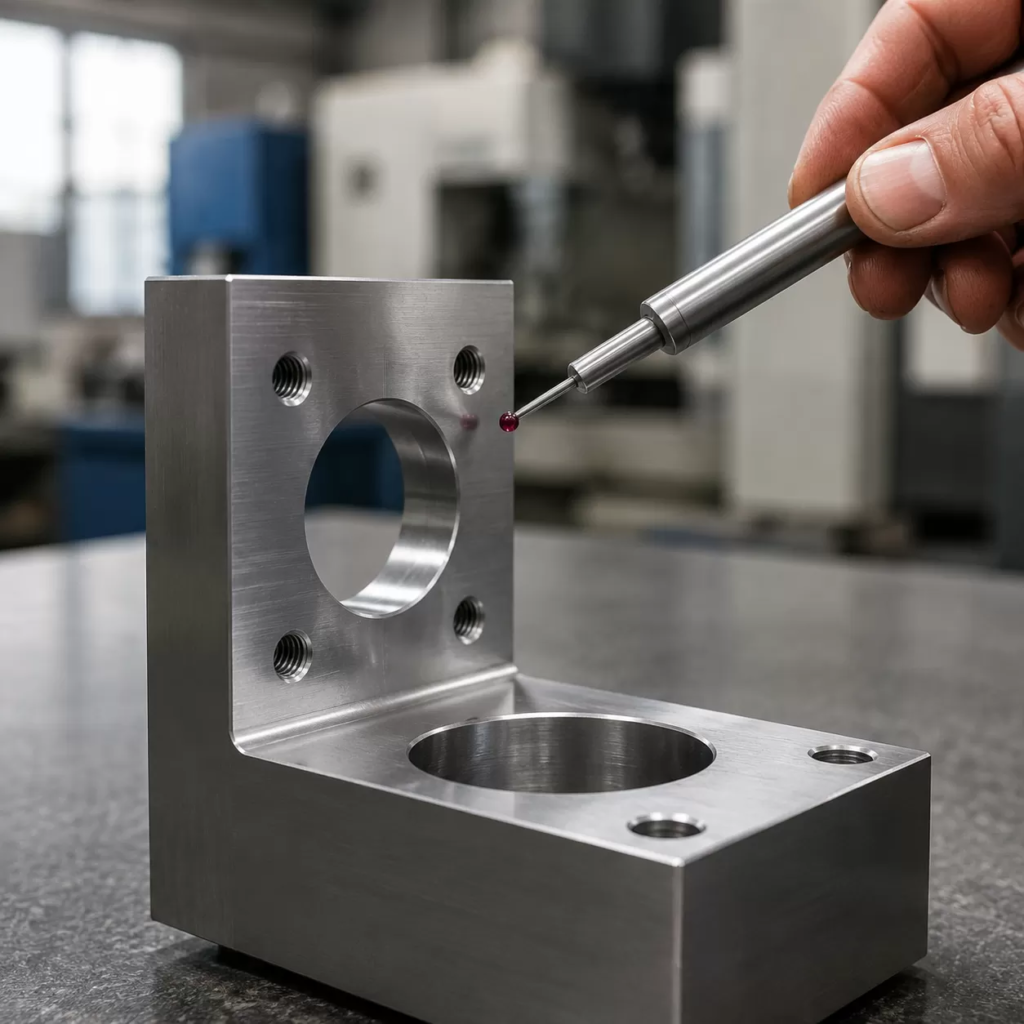
Metrology Equipment: Contact Profilometers vs. Non-Contact Optical Instruments
Choosing the right inspection gear comes down to your part’s geometry, material, and budget.
- Contact Profilometers (Stylus): This is the traditional industry workhorse. A diamond-tipped stylus physically drags across the part surface to map the peaks and valleys. It is highly reliable for standard machined surfaces but can struggle with soft materials that scratch easily, and the physical radius of the tip can sometimes skip over microscopic valleys.
- Non-Contact Optical Instruments: These systems use lasers or light interferometry to scan the surface. They are incredibly fast, map a 3D area rather than a single 2D line, and never touch the part. Optical systems are ideal for delicate components, soft polymers, and ultra-precise optical surfaces, though they can be sensitive to ambient vibration and surface reflectivity.
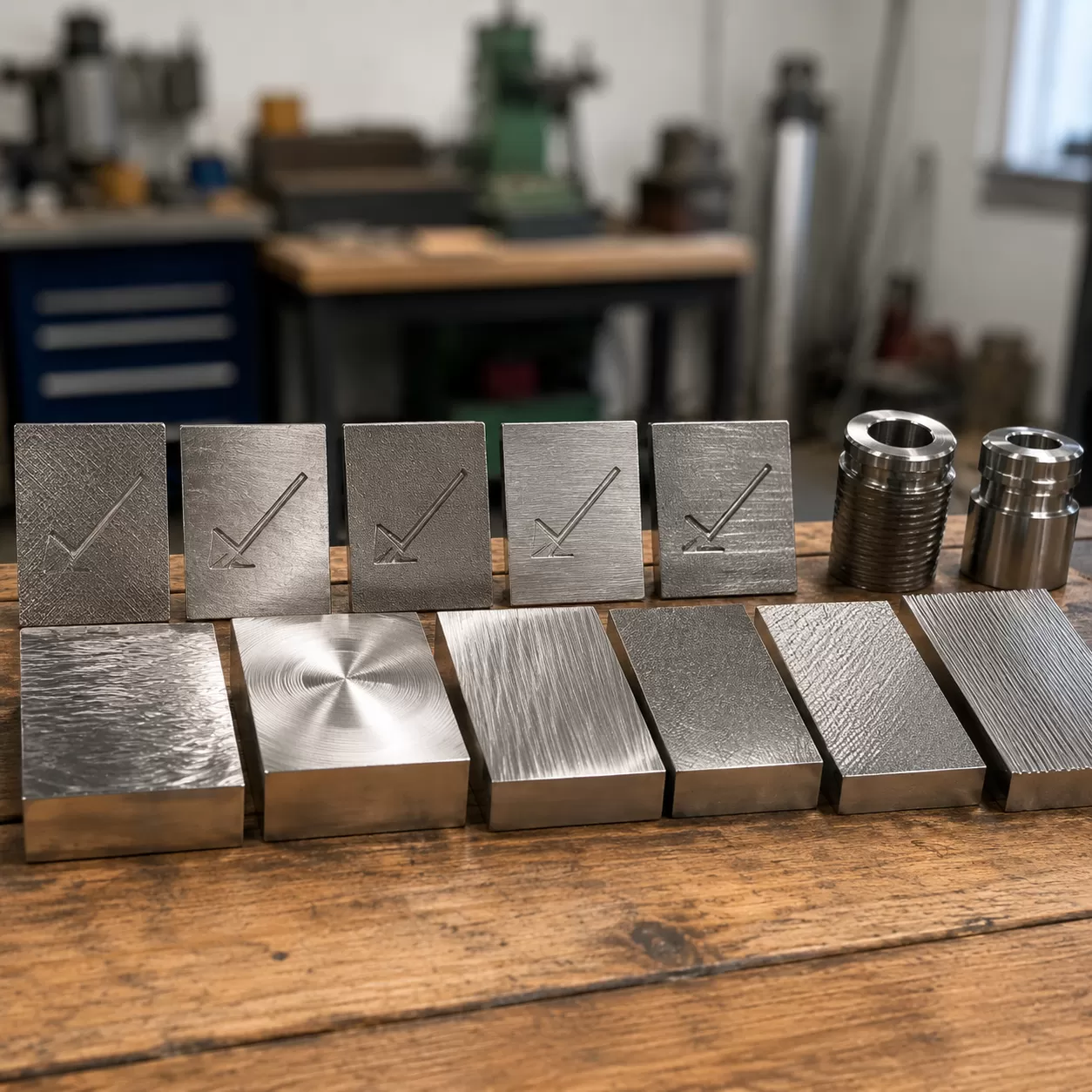
Tactile Surface Comparators for Shop-Floor Validation
You don’t always need a $10,000 gauge to check a part. For quick, routine checks right next to the CNC machine, machinists rely on tactile surface roughness comparators. These are calibrated metal plates that feature sample textures produced by different manufacturing methods like milling, turning, or grinding. By scratching a fingernail across the sample block and then across the machined part, an experienced operator can instantly verify if the part matches the required engineering drawing texture callouts. It is a cost-effective, practical sanity check before parts head to final QA.
The 16% Rule (ISO 4288) vs. Max Rule Implementation
When evaluating your machining surface texture chart measurements, you must follow specific rules to determine if a part passes or fails. Unless a drawing states otherwise, international standards default to specific limits:
| Inspection Rule | How It Works | Best Used For |
|---|---|---|
| The 16% Rule (ISO 4288 / ISO 21920) | Allows a maximum of 16% of all measured values to exceed the specified callout limit. The first measured value must be below 70% of the limit to pass instantly; otherwise, multiple random measurements are taken and averaged. | Standard production runs where minor local surface anomalies do not compromise the overall function of the assembly. |
| The Max Rule (“max” suffix) | Strictly prohibits any measured value from exceeding the limit. If a single peak along the entire evaluation length goes over the callout, the part is rejected. | Critical dynamic seal seats, high-vacuum surfaces, and high-fatigue aerospace components where a single scratch causes failure. |
Engineering Checklists for Releasing Drawings to Production
Before releasing your design to the shop floor, a final review of your surface finish callout notes prevents expensive manufacturing delays and scrap. Missing post-processing changes or leaving out evaluation lengths can ruin a high-precision part. Use this checklist to verify your engineering drawing texture callouts are complete and production-ready.
Pre-Sourcing Checklist: Account for Post-Processing
Surface roughness symbols always apply to the final product unless your drawing notes state otherwise. Plating, anodizing, and bead blasting will fundamentally alter your machined texture.
- Anodizing & Plating: Standard anodizing typically increases surface roughness. If you require a final Ra surface finish guide metric of 32 µin, your machined state prior to coating often needs to be smoother (around 16 to 20 µin).
- Bead Blasting: This process obliterates directional machining lay patterns, replacing them with a non-directional, matte texture. Ensure your base metal casting or machined part has the proper raw surface profile before blasting. For rugged components, understanding the investment casting process helps determine whether the raw casting finish can accept post-processing without additional preliminary machining.
Defining Cutoff Length (λc) Defaults
To ensure accurate inspection with metrology equipment, always define your cutoff wavelength metric. If your CNC surface roughness callout does not explicitly specify the cutoff length ($lambda_c$), the machine shop will default to standard ASME B46.1 or ISO 1302 guidelines.
- Default Standard: For standard machined surfaces with an Ra between 32 µin and 250 µin, the default cutoff length is typically 0.030 inches (0.8 mm).
- Critical Finishes: For ultra-smooth surfaces where Rz roughness parameter or Ra is highly critical, manually specify the cutoff length directly within the long leg of the surface roughness symbols to prevent incorrect profilometer calibration during quality control.
Masking Threads and Critical Assembly Clearances
Never apply a blanket production drawing texture indicator to an entire part without isolating mating features. Roughness specifications can easily wreck tight-tolerance press fits and threaded joints.
- Thread Protection: High-friction or tight-tolerance threads must be masked during secondary blasting or aggressive chemical plating to maintain class fit compliance.
- Clearance Zones: Clearly delineate boundaries using chain lines where precision grinding stops and standard milling begins. This prevents the manufacturing team from wasting cycle time over-machining non-critical clearance zones.
Frequently Asked Questions About Surface Finish Callouts
What is the difference between Ra and Rz in a callout?
Ra and Rz capture entirely different aspects of a surface profile. Using the wrong one can lead to part failure or skyrocketing manufacturing costs.
- Ra (Arithmetic Average Roughness): This is the industry standard for general quality control. It calculates the average height deviation across the entire surface. Because it averages everything out, a single deep scratch won’t heavily impact the Ra value.
- Rz (Maximum Height of Profile): This metric measures the distance between the single highest peak and the lowest valley within a sampling length. It is critical for dynamic sealing surfaces where a single deep scratch causes fluid leaks, or a sharp peak can shred a rubber seal.
How does anodizing affect your drawing surface finish specs?
Anodizing is a conversion coating that alters the final dimensions and topography of your aluminum parts. If your engineering drawing texture callouts specify a tight roughness limit, you must account for how post-processing changes the metal.
- Acid Etching: The chemical cleaning process prior to anodizing typically increases surface roughness, making a smooth machined surface rougher.
- Coating Build-up: Anodizing grows both into and out of the raw material. While it can sometimes bridge micro-scratches, it generally mirrors or exaggerates the underlying substrate roughness.
- The Fix: Always specify on your print whether the surface finish callout applies “before plating” or “after plating” to avoid disputes with your machine shop. For parts requiring both extreme durability and a flawless finish, utilizing high-performance alloys can make a massive difference. You can learn more about how material selection impacts machining and finishing in our titanium aluminum alloy comprehensive guide to properties applications and benefits.
When should you use a material removal prohibited symbol?
The material removal prohibited symbol—designated by a circle modified within the standard 60-degree check-mark—is used when a surface must be left exactly as it is.
Key Rule: This symbol mandates that the surface texture must be produced by the preceding process (like casting, forging, or raw sheet stock) without any subsequent machining.
You should use this specific GD&T surface control symbol when:
- Protecting the structural integrity of a forged skin.
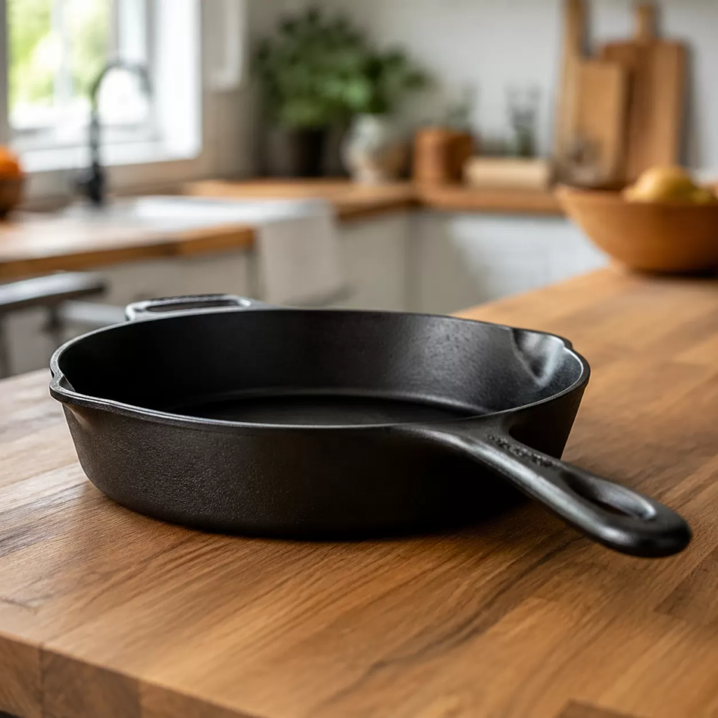
- Utilizing the cost benefits of investment castings where the as-cast finish is perfectly acceptable.
- Ensuring an operator does not machine away a critical datum surface or thin-walled section.